Needle tube oil burning boiler with energy-saving economizer
A technology for oil-fired boilers and economizers, applied in steam boilers, steam generation, lighting and heating equipment, etc., can solve problems such as uneconomical, and achieve the effects of reducing operating costs, improving economic operation levels, and reducing heat loss.
- Summary
- Abstract
- Description
- Claims
- Application Information
AI Technical Summary
Problems solved by technology
Method used
Image

Examples
Embodiment Construction
[0008] The present invention will be further described in detail below in conjunction with the accompanying drawings and preferred embodiments.
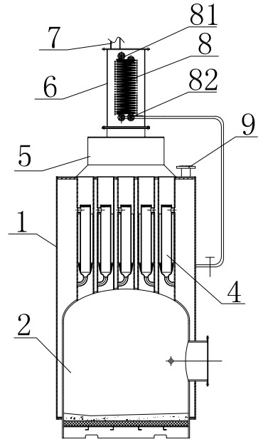
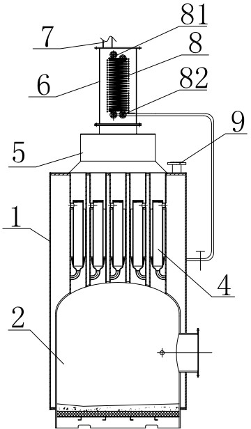
[0009] Such as figure 1 As shown, the structure of the needle-shaped tube oil-fired boiler with an energy-saving economizer mainly includes: a shell 1, a furnace 2 is arranged inside the shell 1, and a number of needle-shaped tube assemblies 4 are connected to the top of the furnace 2. The shell 1 A smoke box 5 is arranged on the top, and the top of the needle tube assembly 4 communicates with the smoke box 5. The top of the housing 1 is also provided with a steam outlet 9, and the smoke box 5 is connected with an energy-saving economical The structure of the energy-saving economizer includes: an energy-saving economizer housing 6, the bottom of the energy-saving economizer housing 6 communicates with the smoke box 5, and the energy-saving economizer housing 6 is connected with an exhaust pipe 7, which is energy-saving and economical...
PUM
 Abstract
Description
Claims
Application Information
PatSnap Eureka turns technology decisions into work you can execute. Powered by our Innovation Knowledge Graph, it runs expert workflows across engineering, life sciences, materials and intellectual property. Get your review-ready output in minutes.


