Humidifier

A humidifier and accommodating chamber technology, applied in ultrasonic humidifiers, air humidification systems, heating methods, etc., can solve the problem that water vapor cannot penetrate very easily, and achieve the effect of improving atomization efficiency

Inactive Publication Date: 2012-07-18
FOSHAN NANHAI KERI ELECTRONICS
View PDF8 Cites 13 Cited by
  • Summary
  • Abstract
  • Description
  • Claims
  • Application Information

AI Technical Summary

Problems solved by technology

[0003] Aiming at the deficiencies of the prior art, the present invention provides a humidifier, especially a humidifier suitable for high power. The first problem to be solved is that the wind sent from the air inlet of the humidifier is not directly blown in one direction. Attack the atomization steam column and basically send all the atomization steam generated by the ultrasonic atomization generator into the mist guide chamber to improve the atomization efficiency and prevent the mist from spreading randomly in the space above the water level line These mist vapors condense into liquid droplets at the connection interface of

Method used


Image

  • Humidifier
  • Humidifier
  • Humidifier

Examples


Embodiment 1

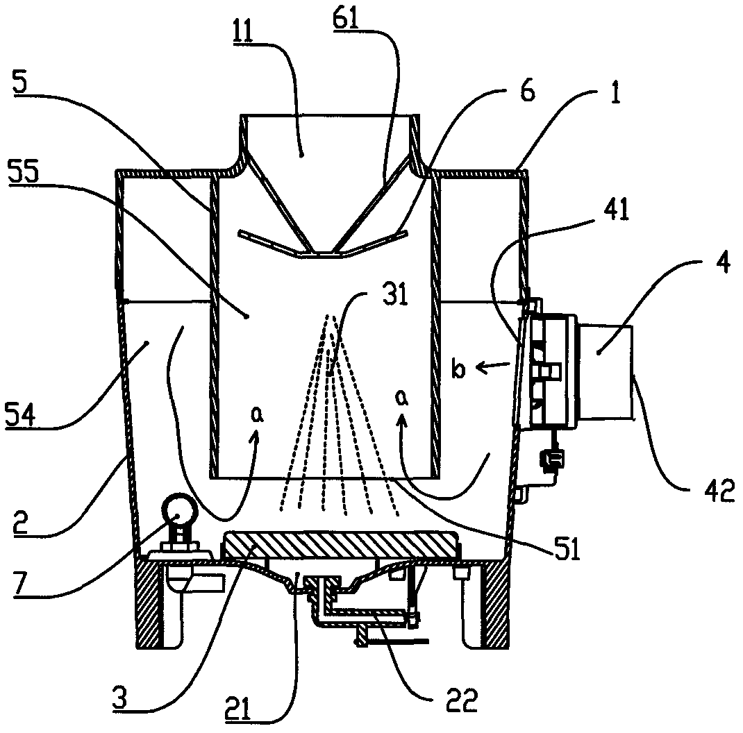
[0028] Such as figure 1 As shown, a humidifier includes an accommodating chamber that can accommodate the atomized liquid, and the accommodating chamber is composed of a liquid holding chamber 2 located below and a cover body 1 covering the liquid holding chamber 2 . The cover body 1 is provided with the mist outlet 11, the inner bottom of the liquid holding chamber 2 is provided with an ultrasonic atomization generator 3 and a float valve 7, and a water inlet (not shown in the figure) is also provided. ). The float valve 7 controls the liquid level of the liquid such as water contained in the liquid holding chamber 2 .

[0029]The cover body 1 is fixedly connected with the mist guide chamber 5 which communicates with the mist outlet 11 and extends to the bottom of the liquid holding chamber 2. The mist guide chamber 5 and the corresponding ultrasonic atomizer The generator 3 is located at the center of the containing cavity.

[0030] The space contained in the mist guiding...

Embodiment 2

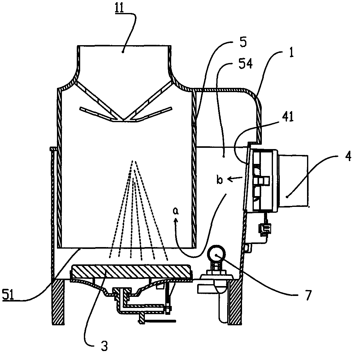
[0039] Such as figure 2 As shown, the difference from the first embodiment is that the mist guiding chamber 5 and the corresponding ultrasonic atomization generator 3 are located at a side position in the accommodating chamber.

Embodiment 3

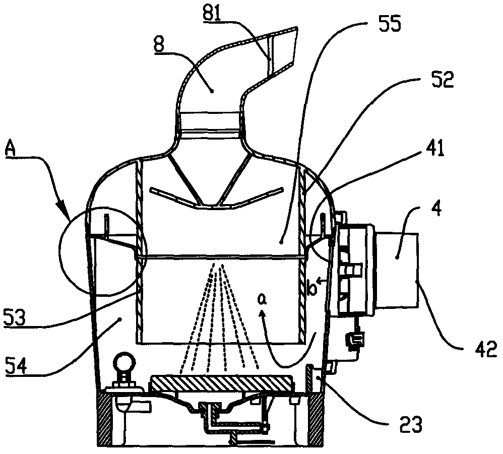
[0041] Such as image 3 and Figure 4 As shown, the difference from Embodiment 1 is that the mist guiding chamber 5 includes a lower channel 53 and an upper channel 52 that are butted up and down. The top skirt 56 of the lower passage 53 is connected to the wall of the liquid holding chamber 2 ; the upper passage 52 is located in the cover 1 and connected to the cover 1 . The skirt 56 covers the upper opening of the liquid holding chamber 2 . In this way, the mist guiding chamber 5 can be manufactured in two stages, thereby reducing mold manufacturing costs without affecting the performance that the mist guiding chamber 5 should have. Secondly, since the lower passage 53 is connected to the wall of the liquid holding chamber 2, the ability of the wall of the liquid holding chamber 2 to bear impacts can be improved.

[0042] A mist guiding pipe 8 is arranged on the upper part of the mist outlet 11, and a grille 81 is arranged inside the mist guiding pipe 8, and the grille 81...


PUM


Abstract

The invention relates to a humidifier for humidifying air. The humidifier comprises an accommodating cavity, a mist outlet and an air inlet, wherein the accommodating cavity can contain atomized liquid, the mist outlet is communicated with the accommodating cavity, the air inlet is communicated with an air blower for supply air to the air inlet, and an ultrasonic atomization generator is arranged in the accommodating cavity. The humidifier is characterized in that a U-shaped air returning channel is arranged in a space above the highest waterline in the accommodating cavity and comprises a mist channel contained by a mist guiding cavity, and a peripheral space positioned on the mist guiding cavity, an outlet part at the upper end of the mist guiding cavity is communicated with the mist outlet, an inlet part at the lower end of the mist guiding cavity is positioned above the atomization generator, the wind from the air inlet passes through the peripheral space of the mist guiding cavity and then bypasses the inlet part at the lower end of the mist guiding cavity to enter the atomization channel of the mist guiding cavity, and the mist guiding cavity is fixedly connected with the wall of the accommodating cavity. The humidifier can be applied to humidifier products.

Description

technical field [0001] The present invention relates to a humidifier for humidifying air, in particular to a device for humidifying indoor air by atomizing water or similar liquids by means of ultrasonic atomization. Background technique [0002] Humidifiers are generally used to humidify indoor air, and similar products are used to treat respiratory diseases or to distribute perfume. Typical structures of humidifiers include side air-flow structure and bottom air-flow structure. Among them, the structure of the side air blowing type is as disclosed in Chinese patents ZL201120143143.X, ZL200820146827.3, and ZL200820043702.8; the structure of the bottom blowing type is as disclosed in Chinese patents ZL201020243515.1 and ZL03270573.5. On the side of the ultrasonic nebulizer, the unilateral air intake mode supplies air to the space above the ultrasonic nebulizer, and the air inlet is often closer to the ultrasonic nebulizer and the water surface. Products with these structur...

Claims


Application Information

Patent Timeline
IPC IPC(8): F24F6/12F24F13/00
CPCY02B30/80Y02B30/70
Inventor 叶卫忠冯锦云朱勇雄邓海涛
Owner FOSHAN NANHAI KERI ELECTRONICS
Why Eureka
Try Eureka