
Absolute propagation time measuring method for ultrasonic flow meter

A technology of propagation time and measurement method, applied in the direction of measuring flow/mass flow, liquid/fluid solid measurement, measuring device, etc., to achieve the effect of reducing running time

Inactive Publication Date: 2012-07-18
BEIJING INSTITUTE OF TECHNOLOGYGY
View PDF5 Cites 20 Cited by
  • Summary
  • Abstract
  • Description
  • Claims
  • Application Information

AI Technical Summary

Problems solved by technology

[0006] In order to solve the problem of low accuracy in measuring absolute travel time, the present invention proposes a method for measuring forward and reverse flow travel time using three transducers, which does not require timing modules and setting threshold values, which is equivalent to converting absolute time measurement For relative time measurement, which reduces the error and improves the measurement accuracy

Method used


Image

  • Absolute propagation time measuring method for ultrasonic flow meter
  • Absolute propagation time measuring method for ultrasonic flow meter
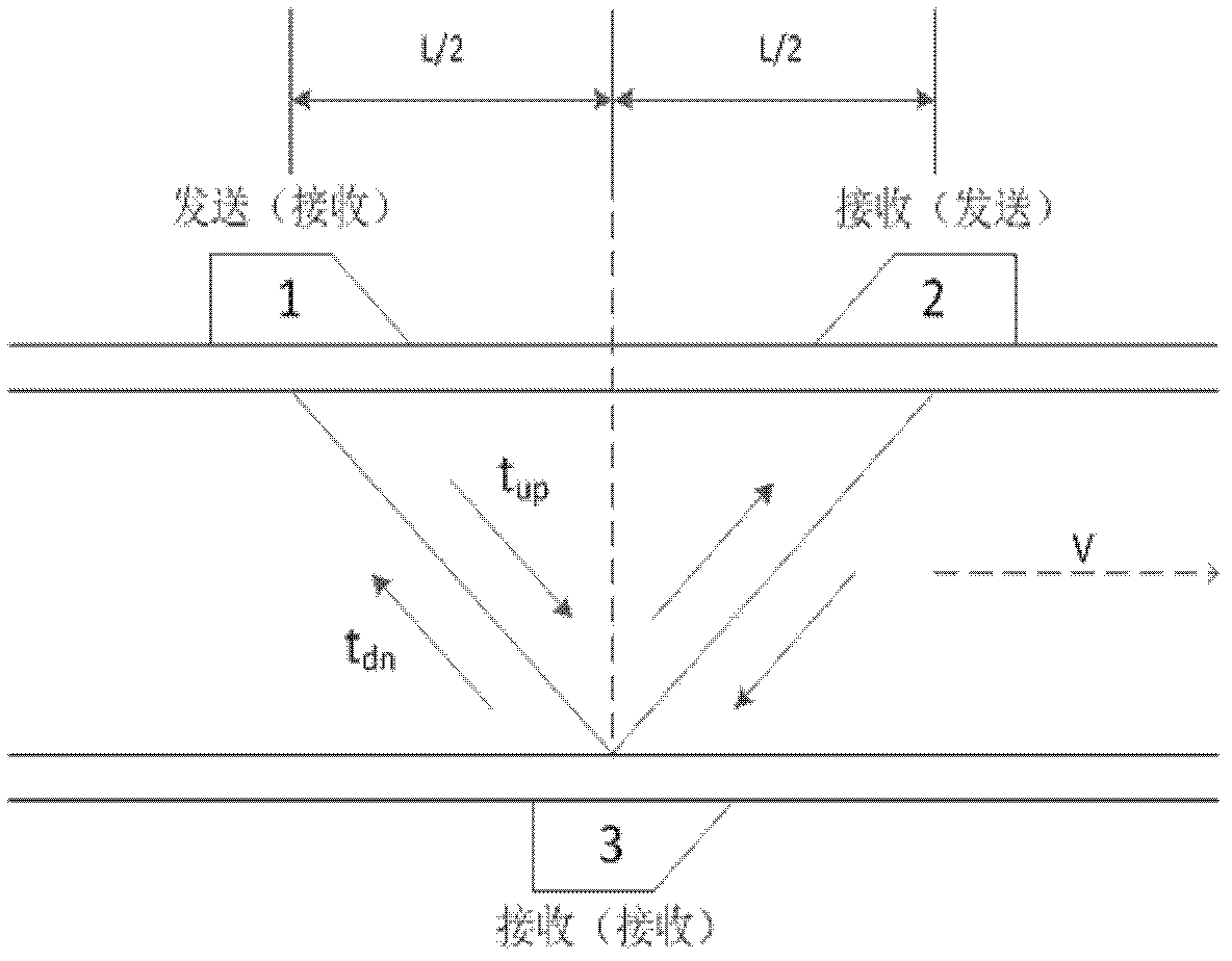
  • Absolute propagation time measuring method for ultrasonic flow meter

Examples


Embodiment Construction

[0021] The present invention will be described in further detail below in conjunction with the accompanying drawings and specific embodiments.

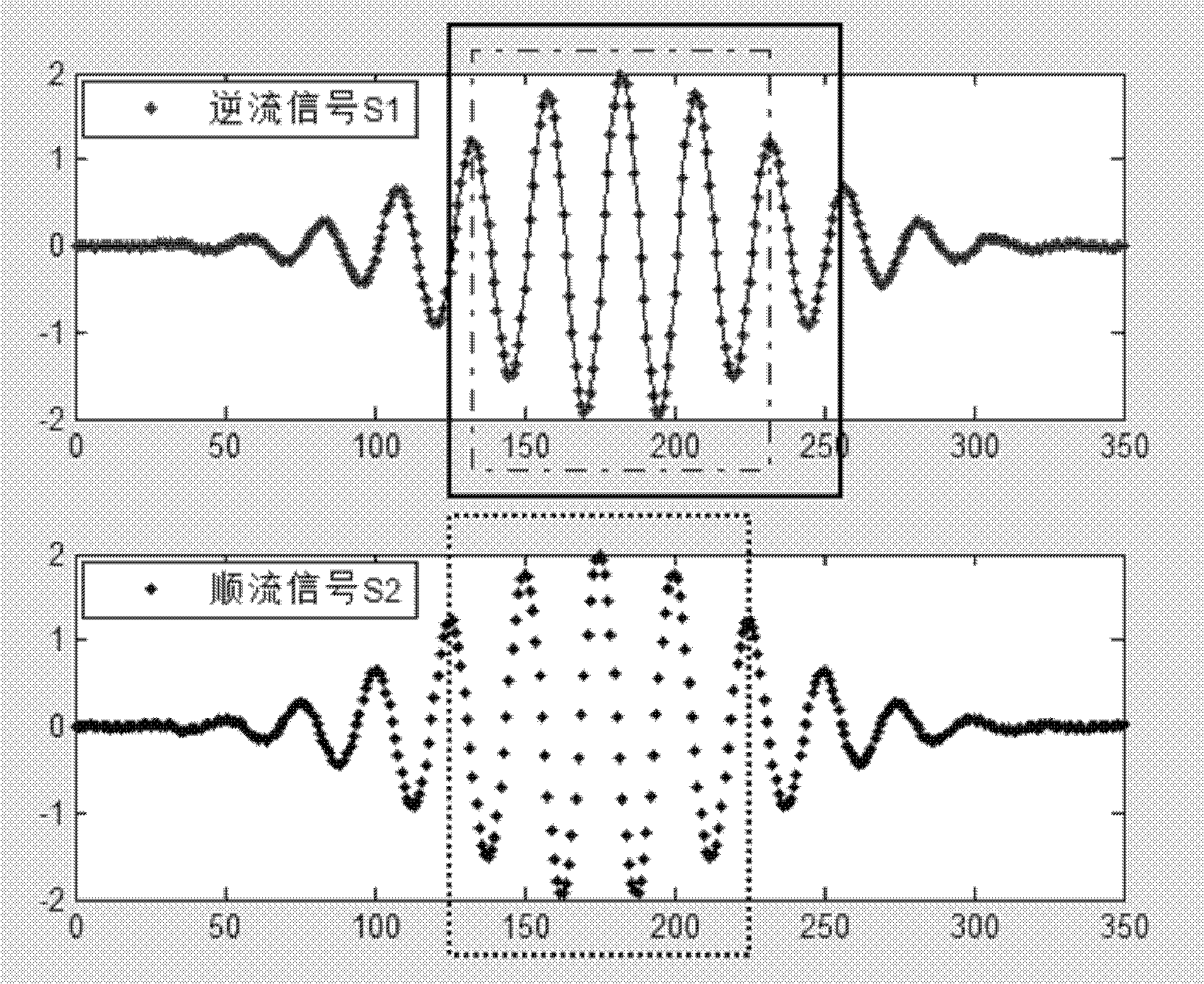
[0022] The present invention provides a method for measuring absolute travel time using 3 transducers and using an improved minimum sum of squares error algorithm.

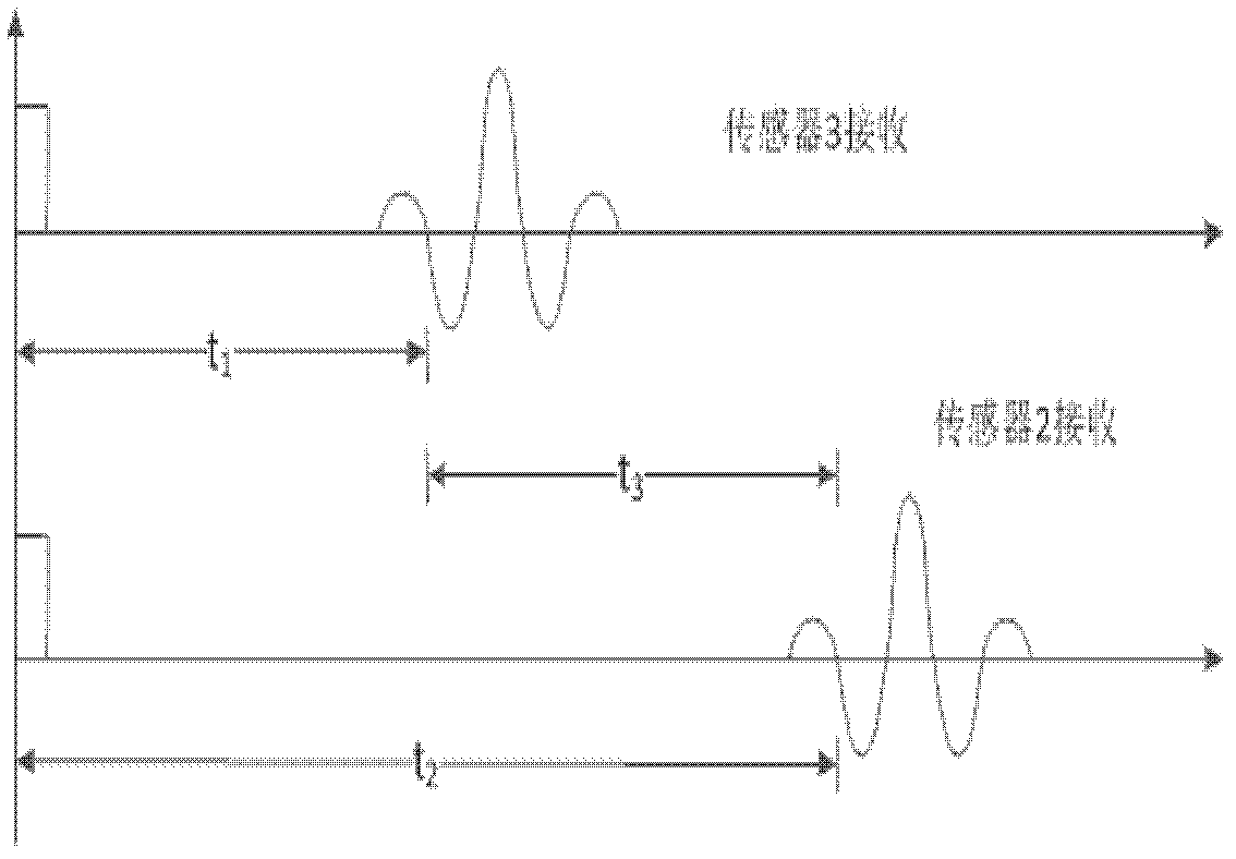
[0023] Such as figure 1 Arrange the transducer installation method as shown, and add a transducer 3 in the middle of the opposite side of the transducer 1 and the transducer 2 under the V-shaped arrangement. Assuming that the distance between transducer 1 and transducer 2 is L, the lateral distance between transducer 3 and transducer 1 and transducer 2 is both L / 2. Transducer 1 and Transducer 2 work alternately in the state of transmitting and receiving, and Transducer 3 only works in the receiving state, that is, Transducer 1 transmits ultrasonic signals, and Transducer 2 and Transducer 3 receive signals at the same time. At this time, the signals received by transduce...


PUM


Abstract

The invention provides an absolute propagation time measuring method for an ultrasonic flow meter. The method comprises the following steps of: setting an energy converter 3 at the center of an opposite side between an energy converter 1 and an energy converter 2, which are arranged in the shape of V; if the distance between the energy converter 1 and the energy converter 2 is set to be L, setting the transverse distance between the energy converter 3 and the energy converter 1 and the transverse distance between the energy converter 3 and the energy converter 2 are both to be L / 2; when the absolute propagation time in case of fair current is measured, leading the energy converter 1 to send out ultrasonic signals, and two receivers, i.e. the energy converter 2 and the energy converter 3, receive the signals; and obtaining the time difference of the signals received by the two receivers by a mode of getting the relative propagation time, wherein a metering result of the time difference is the time that the ultrasonic signals are propagated to the energy converter 2 from the energy converter 3, i.e. obtaining the fair current absolute propagation time in the case that the energy converter 2 and the energy converter 3 are distributed in the shape of Z, wherein the adverse current absolute propagation time measuring method is similar to the fair current absolute propagation time measuring method. The method is used without a timing module, i.e. absolute time measurement is converted into relative time measurement, so that the measurement precision is improved.

Description

technical field [0001] The invention belongs to the technical field of ultrasonic flow measurement, and in particular relates to a method for measuring absolute propagation time by using three transducers and an improved minimum error square sum algorithm for an ultrasonic flowmeter. Background technique [0002] The main basis for the application of ultrasonic technology in flow measurement is: when the ultrasonic wave is incident on the fluid, the ultrasonic wave propagating in the fluid will carry the information of the fluid flow velocity. Ultrasonic flowmeters have various setting methods for the generation, propagation and detection of signals, thus constituting ultrasonic flowmeters with different principles, which can be roughly divided into propagation velocity difference methods (including: time difference method, phase difference method, frequency difference method) method), Doppler method, correlation method, beam shift method, etc. [0003] The transit-time ult...

Claims


Application Information

Patent Timeline
IPC IPC(8): G01F1/66
Inventor 马立玲刘佳王军政沈伟汪首坤赵江波李静
Owner BEIJING INSTITUTE OF TECHNOLOGYGY
Learn More