Indirect evaporation type cooling/condensing device

An evaporative cooling and condensing device technology, applied in the field of evaporative condensers, closed cooling towers, and fluid cooling/condensing devices, can solve the problem of not being able to reduce the temperature of the cooling medium, reduce energy consumption, improve cooling efficiency, The effect of prolonging the use time

Inactive Publication Date: 2008-04-30
TSINGHUA UNIV
View PDF1 Cites 40 Cited by
  • Summary
  • Abstract
  • Description
  • Claims
  • Application Information

AI Technical Summary

Problems solved by technology

Although the evaporative condenser can be converted into an air-cooled condenser by stopping the spraying of the cooling medium water under low temperature conditions, the cooling / condensing efficiency of the evaporative condenser is affected by the ambient air wet bulb during operation in summer. Due to temperature constraints, the temperature of the cooled medium cannot be further reduced

Method used


Image

  • Indirect evaporation type cooling/condensing device

Examples


Embodiment 1

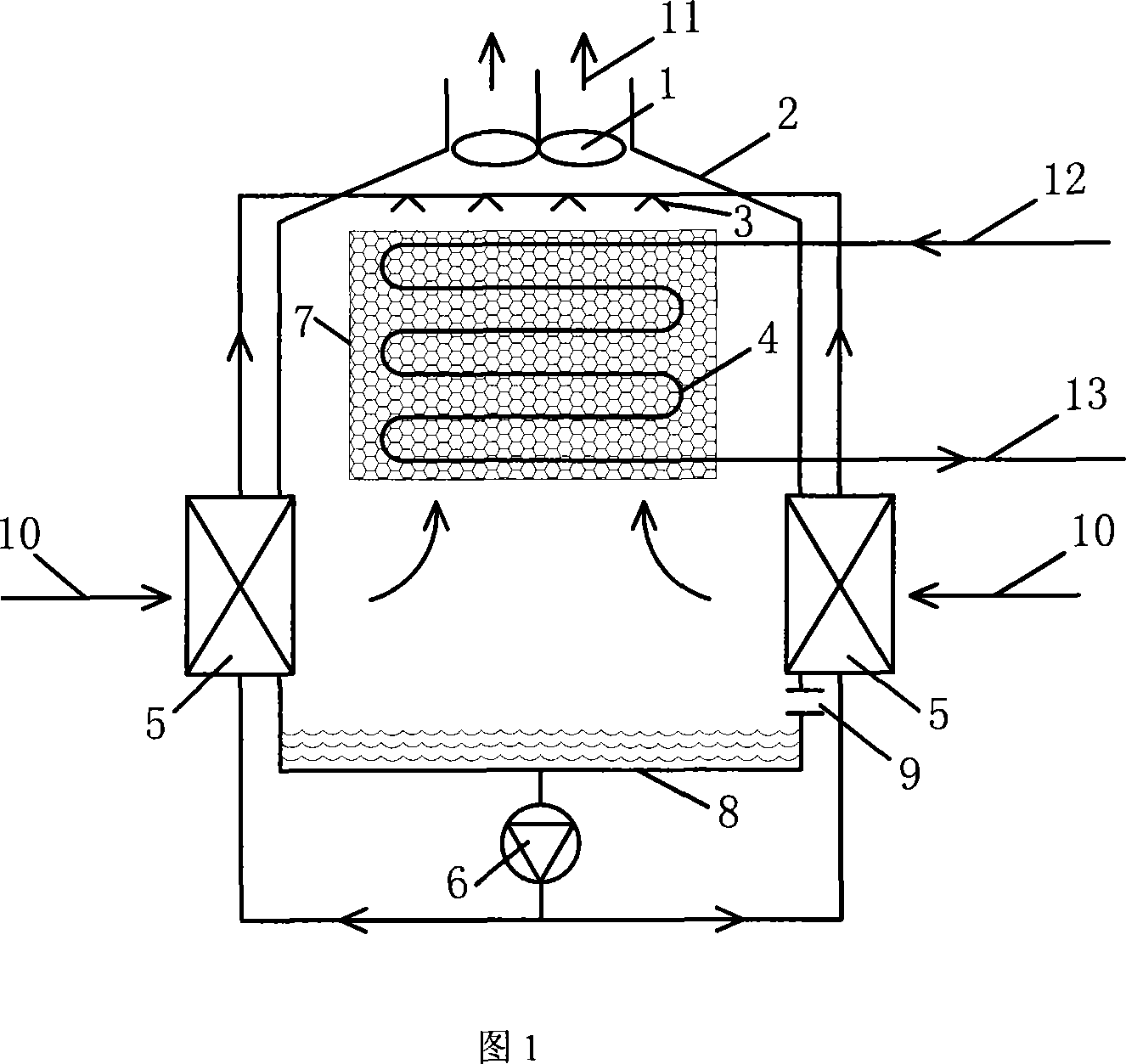
[0020] As shown in Figure 1, an indirect evaporative cooling / condensing device provided by the present invention includes a fan 1, a housing 2, a shower 3, a partition heat exchanger 4, a water pump 6 and a water collecting tray 8; The fan is arranged on the top of the casing, the shower is arranged on the upper part of the casing, the partition heat exchanger is arranged on the lower part of the shower 3, and on the casing wall below the partition heat exchanger An air inlet 10 is provided, and the water collecting tray is arranged at the bottom of the housing. The water collecting tray 8 is provided with a water supply port 9. The water collecting tray is connected to the inlet of the water pump 6 at the lower part of the water collecting tray through a pipeline, and the outlet of the water pump 6 passes through The pipeline is connected to the shower 3; an air-water heat exchanger 5 is arranged at the air inlet 10, and the water side of the air-water heat exchanger is connec...

Embodiment 2

[0030] In the above-mentioned indirect evaporative cooling / condensing device provided by the present invention, when the condensed medium in the partition heat exchanger 4 adopts a high-temperature gas such as a refrigerant or a gas-liquid two-phase fluid, the device can be used as a vapor compression refrigeration unit. System or indirect evaporative condenser for chemical system. Since the refrigeration system or chemical cooling system needs to be refrigerated throughout the year, there are generally the following two operating modes:

[0031](1) Operation mode 1: In summer working conditions, the water pump 6 is turned on, and the circulating water is sprayed, and the high-temperature gas or gas-liquid two-phase fluid such as refrigerant entering the partition heat exchanger 4 dissipates heat to the spraying water to achieve condensation effect. Driven by the fan 1, the outdoor air first passes through the air-water heat exchanger 5 for pre-cooling, and then enters the ho...


PUM


Abstract

An indirect evaporating cooling / condensing device comprises a blower, a shell body, a spraying machine, a dividing wall type heat exchanger, a wind inlet, a water pump and a water collecting plate, and an air-water heat exchanger which is arranged on the wind inlet. The water pump pumps water from the water collecting plate and sends to the water channel of the air-water heart exchanger, cools the environmental air inducted from the wind inlet enters the spraying machine after being cooled; the water which flows out from the spraying machine is sprayed on the outer surface of the dividing wall type heat exchanger, the water flows back to the water collecting plate depending on the gravity; and the cooled medium which enters into the dividing wall type heat exchanger from the entrance is cooled by the water sprayed from the spraying machine and then flow out from the cooled medium exit. The invention not only can be used as the enclosed type cooling tower, but also can be used as the evaporating type condenser; and compared with the prior art, the utility model can make the temperature of the out flowing liquid of the liquid with single-phase much lower in winter, and also can reduce the condensing temperature of the refrigerating and the chemical liquid system; the utility model has cooling / condensing function for the whole year and is useful for the energy saving running of air-conditions, refrigerating and chemical systems.

Description

technical field [0001] The invention relates to a fluid cooling / condensing device adopting an indirect evaporation method, which belongs to the fields of refrigeration, air conditioning and chemical industry, and is especially suitable for evaporative condensers and closed cooling towers. Background technique [0002] Cooling tower is a common cooling equipment in refrigeration, air conditioning and chemical industry. It can cool the high-temperature cooling water discharged from the refrigerator to produce cooling water slightly higher than the wet bulb temperature of the air. However, due to direct contact with the outside world, the conventional open cooling tower During the long-term operation of the system, problems such as water quality deterioration, salt concentration, and large floating water are prone to occur, which will have a certain impact on the life and efficiency of the refrigeration unit. At the same time, it is difficult to provide zero-cost chilled water (...

Claims


Application Information

Patent Timeline
Patent Type & Authority Applications(China)
IPC IPC(8): F25B39/04F28C1/00
Inventor 李先庭石文星王宝龙韩林俊蔡浩王嘉
Owner TSINGHUA UNIV
Why Eureka
Try Eureka