Novel infrared focal plane array imaging optical system

An infrared focal plane and imaging optics technology, applied in the field of readout optical path system, can solve the problems of complex structure, heavy weight and large volume of optical system, and achieve the effect of optimizing readout optical path structure, improving imaging performance, and optimizing integration

Inactive Publication Date: 2012-07-18
BEIJING INSTITUTE OF TECHNOLOGYGY
View PDF3 Cites 0 Cited by
  • Summary
  • Abstract
  • Description
  • Claims
  • Application Information

AI Technical Summary

Problems solved by technology

[0004] The purpose of the present invention is to provide an optimized and integrated uncooled infrared focal plane array for the problems that the optical system of the uncooled infrared focal plane array i

Method used


Image

  • Novel infrared focal plane array imaging optical system
  • Novel infrared focal plane array imaging optical system
  • Novel infrared focal plane array imaging optical system

Examples


Embodiment Construction

[0015] Specific embodiments of the present invention will be described in detail below.

[0016] 1. System composition

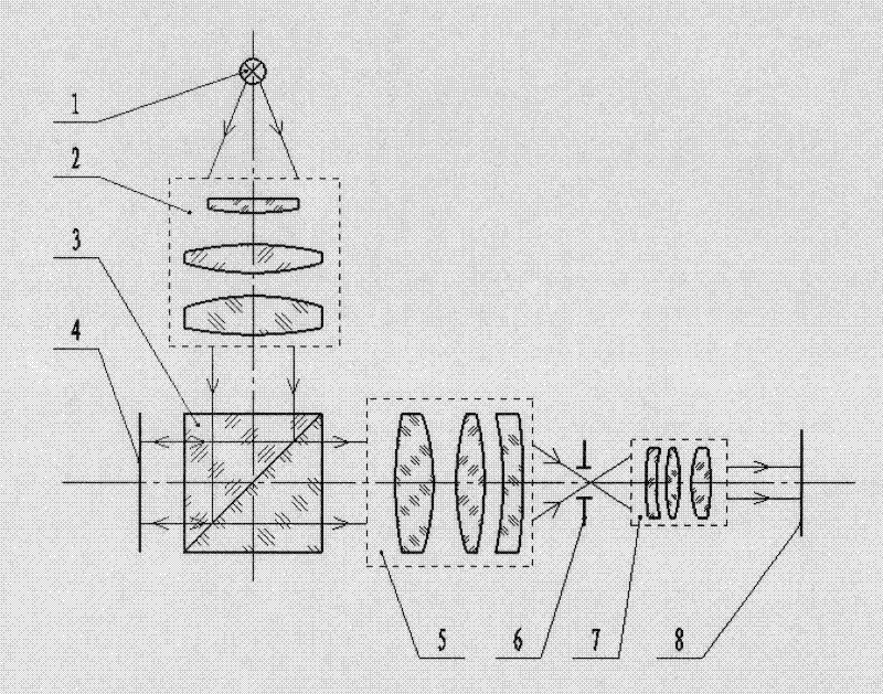
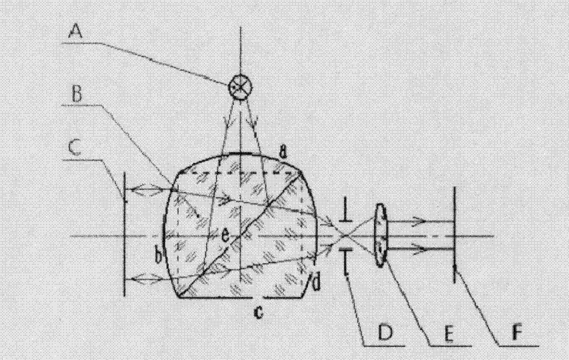
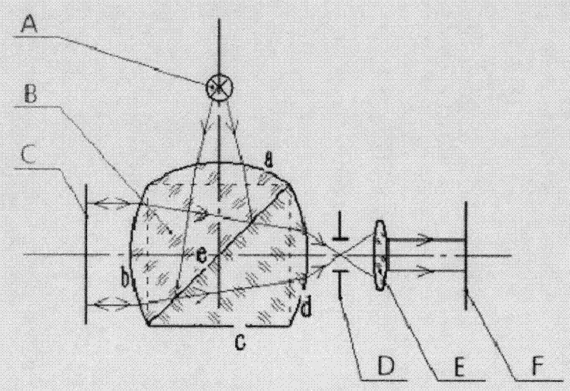
[0017] The novel infrared focal plane array imaging system of the present invention read-out optical path optical system is composed of a light source, a special-shaped prism, an infrared focal plane array, a filter, and an imaging lens. figure 2 Shown.

[0018] 2. Imaging process

[0019] The novel infrared focal plane array imaging system of the present invention reads out the optical path optical system, and its imaging process is as follows figure 2 Shown:

[0020] The divergent light emitted from the light source 1 is condensed by the surface a of the special-shaped prism 2, and is divided into two beams by the bonding surface e of the special-shaped prism 2. One beam is collimated and emitted through the surface b of the special-shaped prism 2, and illuminates the non-infrared focus in parallel. Plane array 3, the other beam exits the optical readout system...


PUM


Abstract

The invention provides a novel infrared focal plane array imaging optical system, which comprises a light source 1, a specially-shaped prism 2, an infrared focal plane array 3, a filter 4 and an imaging lens 5. The novel infrared focal plane array imaging optical system has the imaging characteristics that divergent light is emitted from the light source 1, enters the specially-shaped prism 2, and is converged through a surface a of the specially-shaped prism 2 and split into two beams by an adhesion surface e of the specially-shaped prism 2; one of the beams is collimated and emitted through a surface b of the specially-shaped prism 2 and lightens the infrared focal plane array 3 in parallel, and the other beam is emitted out of an optical read-out system through a surface c of the specially-shaped prism 2; the beam which lightens the infrared focal plane array 3 in parallel is reflected by the infrared focal plane array 3 with infrared image information, re-passes through the surface b of the specially-shaped prism 2 and is converged; converged light penetrates through the surface e of the specially-shaped prism 2, and is converged and emitted through a surface d of the specially-shaped prism 2 and then focused on the filter 4; and light which is filtered by the filter 4 is focused and imaged on an image plane 6.

Description

Technical field [0001] The invention relates to a read-out optical path system of an uncooled infrared focal plane array imaging system, in particular a special-shaped prism structure combining a prism and an aspheric surface is used to integrate the functions of optical parts in the optical system, optimize the read-out optical path structure, and enable The system performance has been further improved, and the volume and weight have been greatly reduced. Background technique [0002] The optical readout micro-cantilever focal plane array (FPA) thermal imaging system based on MOEMS technology is the process of realizing infrared light-thermomechanical deformation-irradiating visible light reflected light intensity change-restoring the image. In theory, the NETD of the optical readout infrared focal plane array imaging system can be far superior to the electrical readout infrared focal plane array imaging system. However, according to the current domestic and foreign technical da...

Claims


Application Information

Patent Timeline
IPC IPC(8): G01J5/08G02B7/18
Inventor 赵跃进褚旭红董立泉刘小华于晓梅惠梅武红龚诚
Owner BEIJING INSTITUTE OF TECHNOLOGYGY
Why Eureka
Try Eureka