Leakage check method for main heat exchanger leakage of air separation plant

A technology of main heat exchanger and air separation equipment, which is applied in the direction of liquid tightness measurement by using liquid/vacuum degree, and by measuring the increase and decrease rate of fluid, etc. Oxygen purity exceeds the normal index and other problems to achieve the effect of improving efficiency and reducing losses

Inactive Publication Date: 2012-07-18
ANHUI HUAIHUA
View PDF1 Cites 6 Cited by
  • Summary
  • Abstract
  • Description
  • Claims
  • Application Information

AI Technical Summary

Problems solved by technology

[0003] When the main heat exchanger leaks, the purity of high-pressure nitrogen and oxygen will exceed the normal index, and often fluctuate without obvious regular changes, which will bring serious safety hazards to the subsequent production pr

Method used


Image

  • Leakage check method for main heat exchanger leakage of air separation plant
  • Leakage check method for main heat exchanger leakage of air separation plant

Examples


Embodiment 1

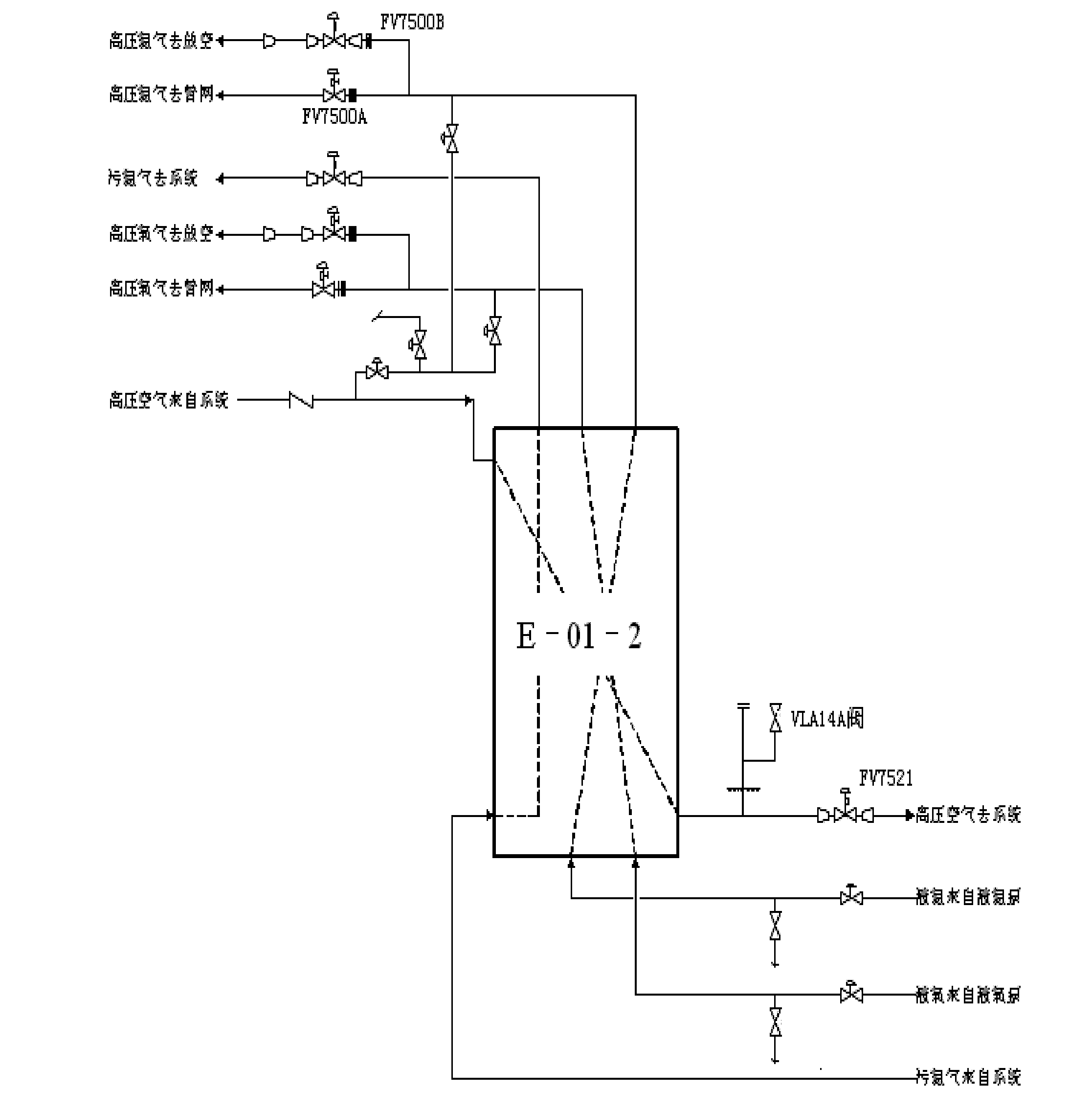
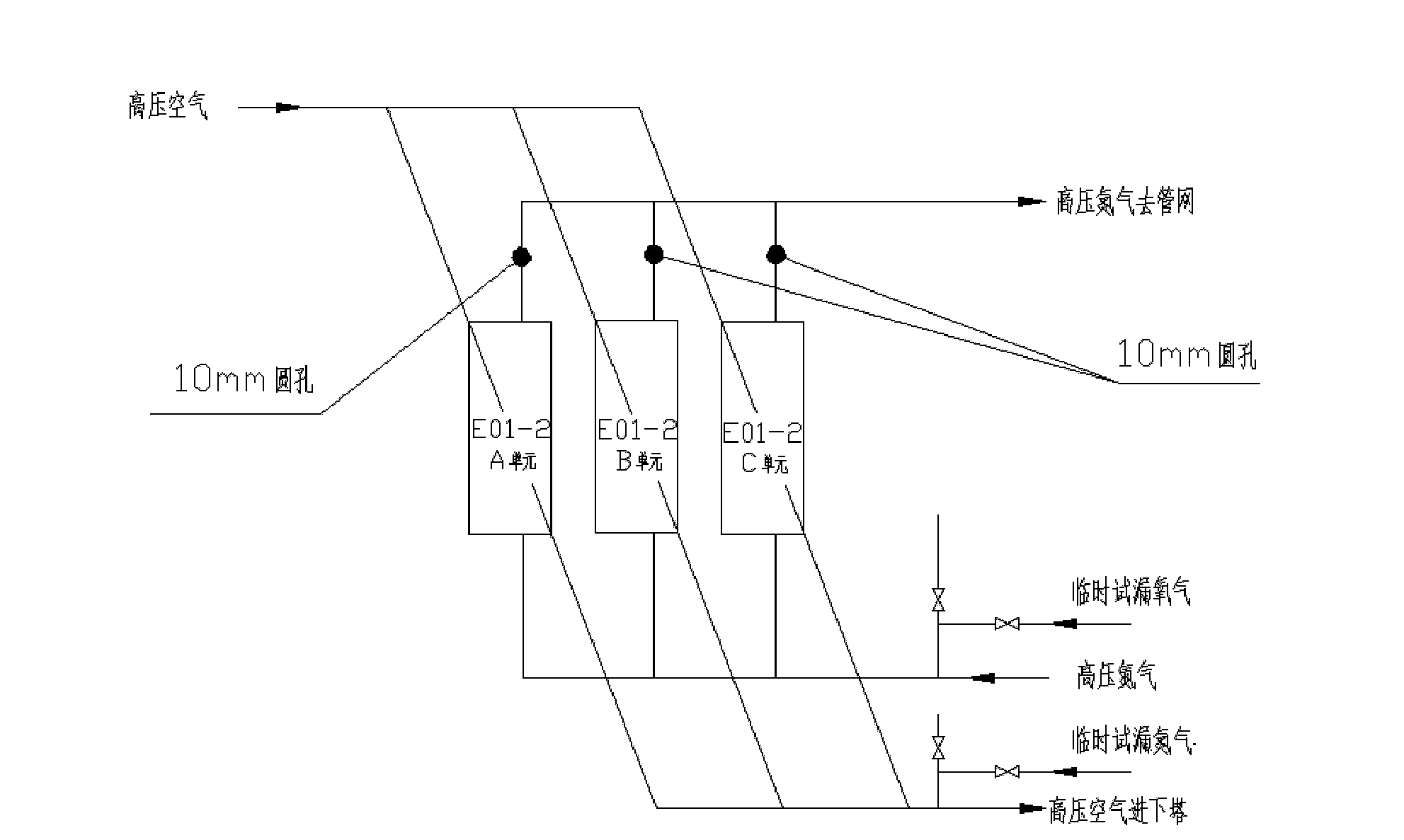
[0020] In the driving state, the high-pressure nitrogen connection temporary pipeline of another set of air separation unit is introduced into the online analyzer, and the data is compared and analyzed to eliminate the instrument error; then, after cleaning the cold box, it is closed by adding a flange blind plate The liquid nitrogen intake manifold at the bottom of the main heat exchanger and the high-pressure nitrogen exhaust manifold at the top; if there are other inlet and outlet pipes on the equipment, such as liquid nitrogen intake pipes and discharge pipes, they should also be closed. Close the inlet valve of the high-pressure air main pipe at the top of the main heat exchanger and the discharge valve of the high-pressure air main pipe at the bottom, and then introduce the high-pressure nitrogen of another set of air separation unit through the main heat exchanger cold-end air main discharge valve (VLA14A valve) as a temporary Nitrogen leak test, the pressure of the nitr...

Embodiment 2

[0022] In the driving state, the high-pressure nitrogen connection temporary pipeline of another set of air separation unit is introduced into the online analyzer, and the data is compared and analyzed to eliminate the instrument error; then, after cleaning the cold box, it is closed by adding a flange blind plate The liquid nitrogen intake manifold at the bottom of the main heat exchanger and the high-pressure nitrogen exhaust manifold at the top; if there are other inlet and outlet pipes on the equipment, such as liquid nitrogen intake pipes and discharge pipes, they should also be closed. Close the inlet valve of the high-pressure air main pipe at the top of the main heat exchanger and the discharge valve of the high-pressure air main pipe at the bottom, and then introduce the high-pressure nitrogen of another set of air separation unit through the main heat exchanger cold-end air main discharge valve (VLA14A valve) as a temporary Nitrogen leak test, the pressure of the nitr...


PUM


Abstract

The invention relates to a leakage check method for the main heat exchanger leakage of an air separation plant. After an instrument error is removed and ice chest skimming sand is removed, the leakage check method comprises the following steps: sealing a liquid nitrogen inlet manifold at the bottom of a main heat exchanger and a high-pressure nitrogen gas discharging manifold at the top of the main heat exchanger; shutting off a high-pressure air manifold inlet valve at the top of the main heat exchanger and a high-pressure air manifold discharging valve at the bottom of the main heat exchanger; introducing high-pressure temporary leakage check nitrogen by the high-pressure air discharging manifold at the bottom of the main heat exchanger, wherein the pressure of the temporary leakage check nitrogen is above 3.2MPa; and finally, analyzing purity pollution. The method can be used for quickly and accurately judging which unit has air leakage, and therefore maintenance efficiency can be improved and loss brought by equipment faults is reduced.

Description

technical field [0001] The invention relates to the field of chemical industry, in particular to a leak testing method for a main heat exchanger of an air separation plant. Background technique [0002] The air separation plant uses air as the raw material, turns the air into a liquid state by means of compression cycle deep freezing, and then gradually separates inert gases such as oxygen, nitrogen and argon from the liquid air through rectification. Usually includes: power system (compressor), purification system, heat exchange system, rectification system, transportation system, storage system and control system, etc. The heat exchange system is mainly composed of heat exchangers. The main heat exchanger is divided into three units. The top of the process medium has one inlet and three outlets, which are: high-pressure air 7.0MPa (inlet), high-pressure oxygen 6.5MPa (outlet), high-pressure Nitrogen 3.8MPa (out), low-pressure dirty nitrogen 36Kpa (out). The bottom is: th...

Claims


Application Information

Patent Timeline
IPC IPC(8): G01M3/02G01M3/32
Inventor 苏传好郭勇陈方林周永林李明
Owner ANHUI HUAIHUA
Why Eureka
Try Eureka