Signal processing method by adopting public processing circuit during collection of alternating-current voltage and current

An AC voltage and circuit processing technology, applied in the field of signal processing, can solve the problems of requiring a large number of components to measure and have large limitations, and achieve the effect of reducing the number of circuits and components, saving circuit costs, and reducing the area of ​​​​the circuit board

Inactive Publication Date: 2012-07-18
西安爱邦电子系统有限公司
5 Cites 4 Cited by

AI-Extracted Technical Summary

Problems solved by technology

[0006] The present invention provides a signal processing method using a common processing circuit when collecting AC voltage and current, which mainly solves the problem that di...

Abstract

The invention provides a signal processing method by adopting a public processing circuit during collection of alternating-current voltage and current, which mainly solves the problem that when alternating-current voltage and current are collected in the prior art, different signal processing channels are adopted, a large number of elements are needed for performing measurement, and limitation is large. The signal processing method by adopting the public processing circuit during the collection of the alternating-current voltage and the current includes the following steps: 1] converting signals of voltage and current to be measured into current signals with a consistent range, and inputting the signal into a step 2 to be processed after conversion is finished; 2] sampling the current signals processed in the step 1, and converting the current signals processed in the step 1 into proportional voltage signals after sampling is finished. The signal processing method greatly saves circuit cost, reduces area of a circuit board, and multiplies flexibility of channel input amount.

Application Domain

Technology Topic

Power flowSignaling process +3

Image

  • Signal processing method by adopting public processing circuit during collection of alternating-current voltage and current
  • Signal processing method by adopting public processing circuit during collection of alternating-current voltage and current
  • Signal processing method by adopting public processing circuit during collection of alternating-current voltage and current

Examples

  • Experimental program(1)

Example Embodiment

[0026] In order to enable the AC voltage and current to share the same signal processing channel, the present invention provides a signal processing and switching method, which is specifically described as follows:
[0027] The signal processing method using a common processing circuit when collecting AC voltage and current includes the following steps:
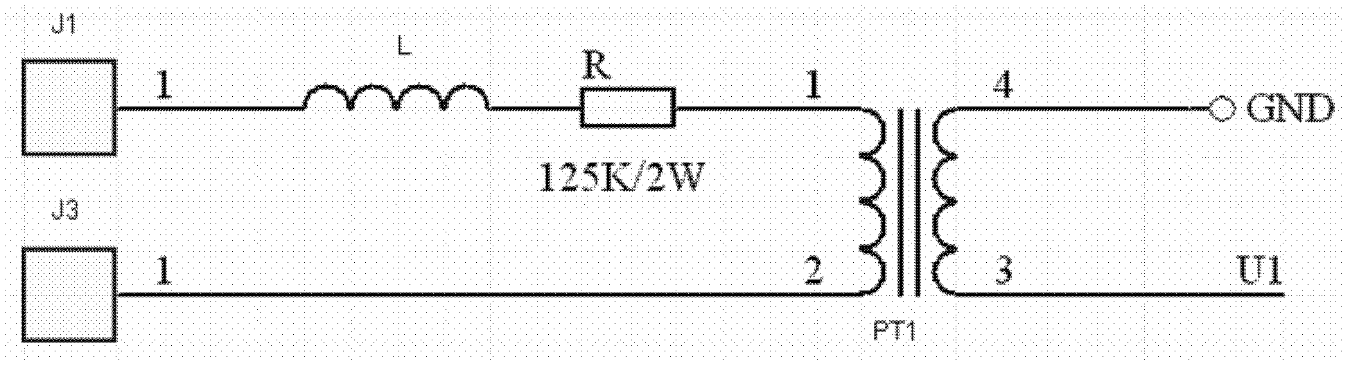
[0028] 1] Transform the measured voltages into weak voltage signals through the signal conversion circuit, and input the signals to step 3 for processing after the conversion is completed;
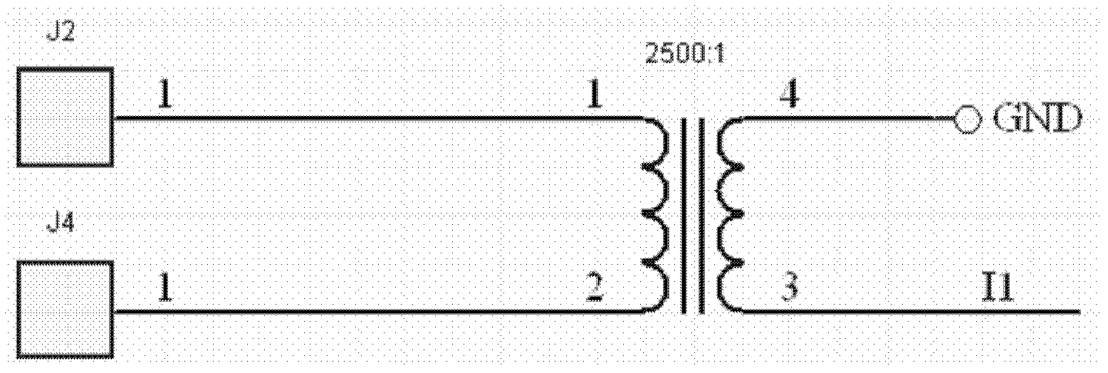
[0029] If you want to use the same signal processing circuit to process AC voltage and current signals, you need to first convert the measured voltage and current signals into the same type of signal, and the ranges are consistent. For this reason, for the measured AC voltage signal, it is transformed into a proportional weak voltage signal through a signal conversion circuit. The signal conversion circuit can be realized by means of voltage transformer, resistor divider, and operational amplifier step-down.
[0030] 2] The measured currents are converted into weak current signals by the signal conversion circuit, and after the conversion is completed, they are converted into proportional weak voltage signals by the sampling circuit, and the weak voltage signals are input to step 3 for processing;
[0031] If you want to convert the measured current into a weak voltage signal with the same signal range as the signal obtained in step 1, first convert the measured current into a weak current through a current conversion circuit. The above current conversion circuit can be through current transformers, current clamps, and shunts. The low current signal can be converted into a proportional voltage signal after the sampling circuit. The sampling circuit can be a resistor, an I/V conversion circuit based on an operational amplifier, etc.
[0032] 3] After steps 1 and 2 are completed, select the signal to be collected for collection, which is specifically selected by using the switching structure of the AC voltage and current common signal processing circuit. Image 6.
[0033] If you use the same signal processing circuit to process the weak voltage signals obtained in steps 5 and 6, you need to resort to Image 6 The switching structure shown is implemented. Image 6 Shows the use of a single-pole double-throw switch to realize the method of selecting one of two voltage or current signals into the later signal processing circuit. The switching structure can also be implemented using relays, analog switches, transfer switches, circuit board switches, etc.
[0034] In the same way, if multiple signals need to be processed by the same signal processing circuit, they can be realized by using a switch, relay, analog switch, circuit board switch, etc. with the function of selecting one more than one.
[0035] The present invention will be described in detail below in conjunction with specific embodiments:
[0036] 1] Convert the measured voltage and current signals into current signals with the same range, and input the signals to step 2 for processing after the conversion is completed;
[0037] If the same signal processing circuit is used to process the AC voltage and current signals, the measured voltage and current signals need to be converted to the same type of signal first, and the ranges are consistent. To this end, for the measured AC voltage signal, use a voltage transformer to convert it to output a current signal. The circuit is like figure 1 Shown figure 1 Among them, PT1 is a transformer with a current ratio of 1:1. The measured AC voltage is connected from terminals J1 and J3. Set the measured voltage range to be 0~500V. If you want the maximum output current to be 4mA, then the sampling resistance is 500V/4mA=125KΩ; the current conversion circuit is relatively simple, choose a suitable one A current transformer or current clamp is sufficient. Set the measured current range to 0~10A. If the maximum output current is expected to be 4mA (should be consistent with the output range of the voltage conversion circuit), the transformer transformation ratio is 10A/4mA = 2500:1, such as figure 2 Shown
[0038] 2] Sampling the current signal processed in step 1, after sampling, convert the current signal processed in step 1 into a proportional voltage signal; after converting the voltage and current into a weak current signal in the same range, perform Take a sample and convert it into a proportional voltage signal to facilitate filtering and amplifying processing in the later stage. The circuit is like image 3 Shown
[0039] Suppose the voltage range required by the subsequent circuit is -5V~+5V, considering the multiple relationship between the maximum value of AC and the effective value, then the sampling resistance In actual applications, a margin of more than 10% should be left, so the actual resistance R = 750Ω; OUT output is in the range of -5V ~ +5V, followed by filtering and amplifying circuits, which will not be given here.
[0040] After step 2 is completed, select the signal to be collected for collection, which is specifically selected by using the switching structure of the AC voltage and current common signal processing circuit, which is described below in conjunction with specific embodiments:
[0041] There are 4 voltage signals and 4 current signals, which share 4 signal processing channels. Each of the 4 voltage signals is transformed into 4 signals of U1, U2, U3, U4 by the voltage transformer; the 4 current signals are transformed into 4 signals of I1, I2, I3, I4 etc. by the current transformer; 4 signal processing The input of the circuit is UI1, UI2, UI3, UI4.
[0042] The switching structure of the AC voltage and current common signal processing circuit can be used to switch the connection of the sampling circuit and different input signals, so as to realize the simultaneous acquisition of the following 5 signal combinations: 1, 4U: U1, U2, U3, U4; 2, 3U1I: U1, U2, U3, I4; 3, 2U2I: U1, U2, I3, I4; 4, 1U3I: U1, I2, I3, I4; 5, 4I: I1, I2, I3, I4
[0043] As attached Figure 4 As shown, a single-layer 4-pole, 6-throw circuit board switch is used. Among them, the black concentric arcs are the exposed wires on the PCB printed board, and each two adjacent concentric arcs from the outer ring to the inner ring is a group, which is divided into 4 groups. Each group uses a short-connected V-piece to short-circuit it. The V-piece is rotated by a rotary switch. The positions where the rotary switch can stay are OFF, 4U, 3U1I, 2U2I, 1U3I, 4I.
[0044] Attached Figure 4 For the state of the V slice when the selector switch stays at the "2U2I" position, the 4 V slices will short-circuit U1-UI1, U2-UI2, I3-UI3 and I4-UI4 respectively, and then the signals U1, U2, I3 And I4 introduces the processing circuit.

PUM

no PUM

Description & Claims & Application Information

We can also present the details of the Description, Claims and Application information to help users get a comprehensive understanding of the technical details of the patent, such as background art, summary of invention, brief description of drawings, description of embodiments, and other original content. On the other hand, users can also determine the specific scope of protection of the technology through the list of claims; as well as understand the changes in the life cycle of the technology with the presentation of the patent timeline. Login to view more.

Similar technology patents

Classification and recommendation of technical efficacy words

Why Eureka
Try Eureka