
Gas scrubber having an integrated heat exchanger

A gas scrubber and heat exchanger technology, applied in heat exchange equipment, gas treatment, indirect heat exchangers, etc., can solve the problems of blocked pipes, high cleaning consumption, etc., and achieve the effect of small pressure loss

Active Publication Date: 2012-07-18
LURGI
View PDF6 Cites 2 Cited by
  • Summary
  • Abstract
  • Description
  • Claims
  • Application Information

AI Technical Summary

Problems solved by technology

The disadvantage of this design is the tendency for the tubes to become clogged and thus the high cleaning consumption

Method used


Image

  • Gas scrubber having an integrated heat exchanger
  • Gas scrubber having an integrated heat exchanger
  • Gas scrubber having an integrated heat exchanger

Examples


Embodiment Construction

[0024] Example 1:

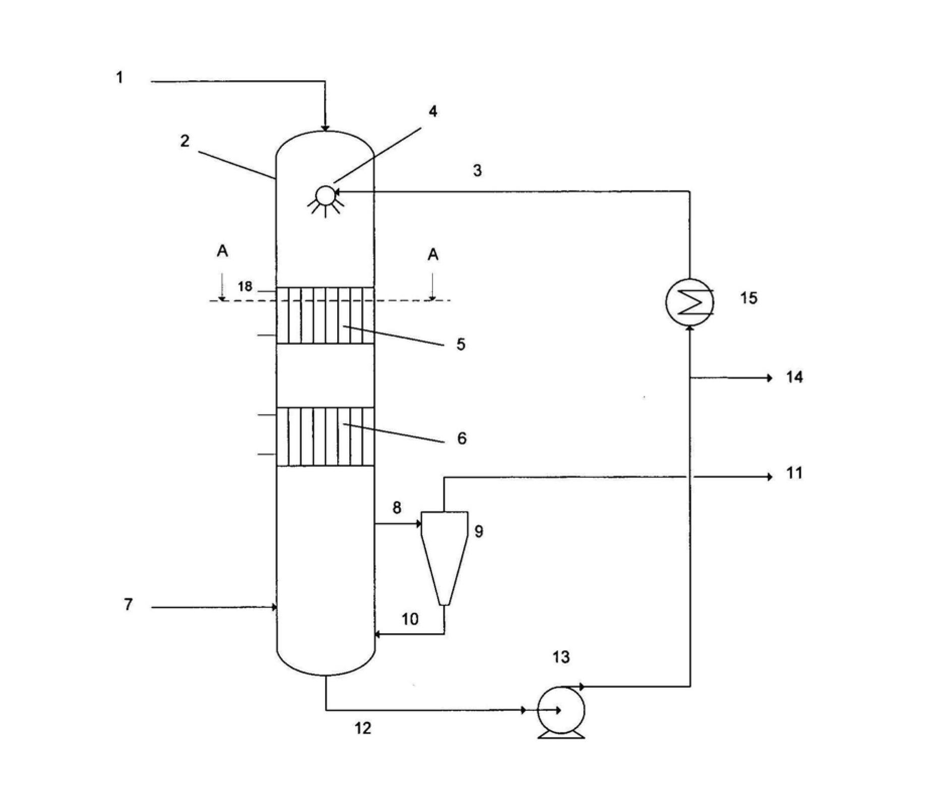
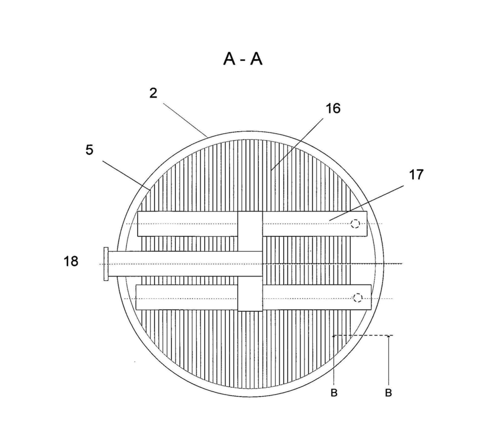
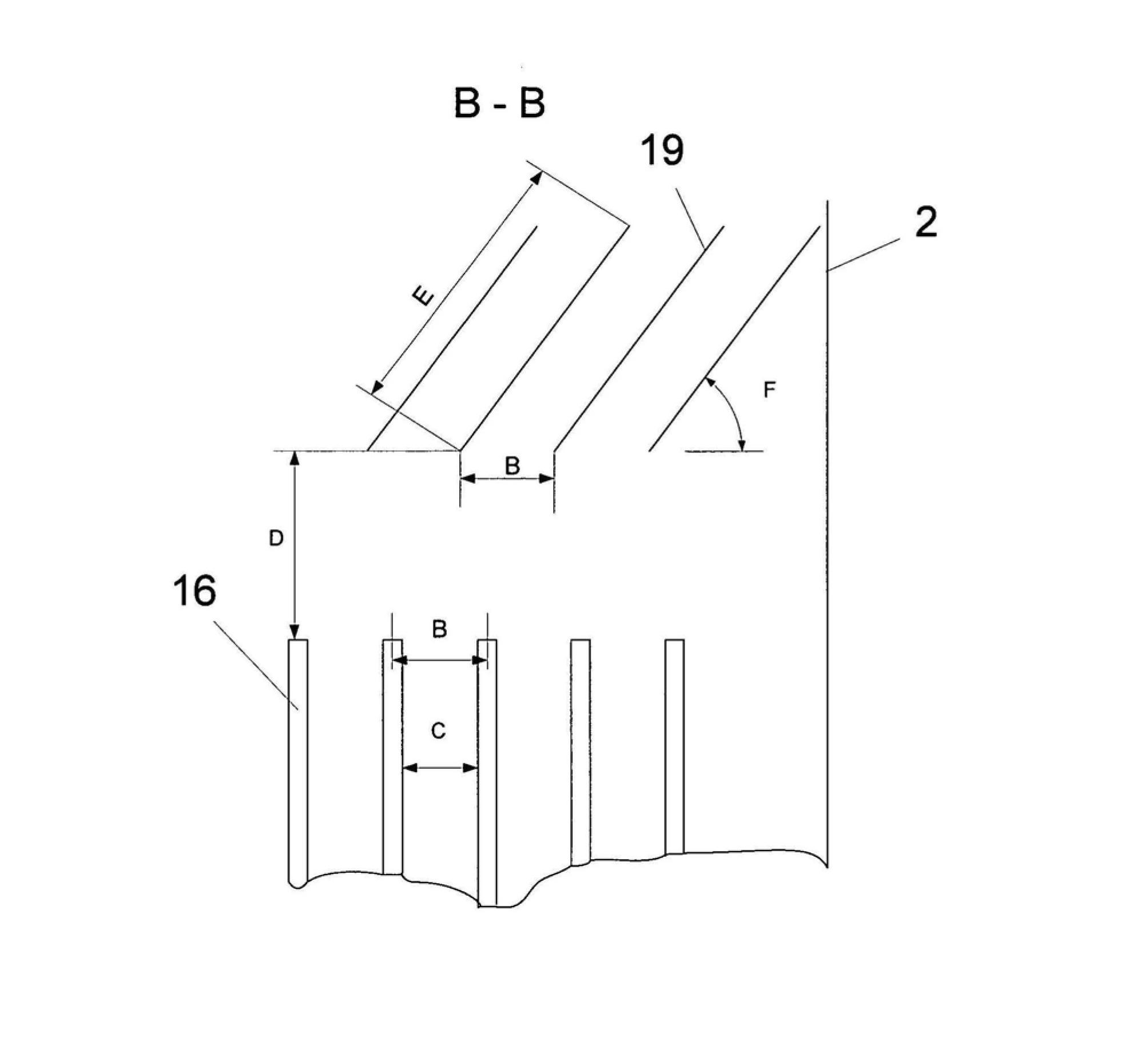
[0025] exist figure 1 shows a plant for scrubbing the process off-gases of melamine synthesis mainly consisting of ammonia and carbon dioxide as well as urea residues and isocyanic acid residues, with gas scrubber (2), separator (9), circulation pump (12) and cooler (13). The process off-gas stream ( 1 ) from the melamine synthesis, not shown, enters at the head of a cylindrical gas scrubber ( 2 ). As stream (3), the urea-containing melt used as scrubbing liquid is introduced into the gas scrubber. The scrubbing liquid (3) is dispersed in the process off-gas (1) by means of a nozzle system (4), forming a gas / liquid mixture. Next, the gas / liquid mixture flows through heat exchangers (5) and (6). The heat exchanger is constructed according to the invention from heat fins. To cool the gas / liquid mixture, there is boiling water with a temperature of 125°C in the heat plate. The water vapor generated by the absorbed heat leaves the heat fins via the colle...


PUM


Abstract

The invention relates to a gas scrubber, equipped with heat exchanger surfaces constructed from thermal sheets, suitable for cooling and purifying a hot gas, while avoiding excessive thermal loading of the scrubbing liquid.

Description

technical field [0001] The invention relates to a gas scrubber with one or more heat exchangers integrated in the device housing for cooling a gas / liquid mixture of gas to be cleaned and scrubbing liquid. [0002] Furthermore, the invention relates to a method for using such a gas scrubber. Background technique [0003] Gas scrubbers and methods for cooling and cleaning are well known. [0004] A heat exchanger needs to be integrated directly in the scrubber housing in the flow of the gas / liquid mixture in special applications for gas scrubbers where the temperature of the gas to be cooled Above the temperature of the washing liquid and at the same time the heating of the washing liquid should be prevented as much as possible in order to avoid evaporation or chemical decomposition of the washing liquid. [0005] A corresponding situation for the treatment of process offgases from melamine synthesis is described in German patent application document 2525781. Here, a gas sc...

Claims


Application Information

Patent Timeline
Patent Type & Authority Applications(China)
IPC IPC(8): B01D53/18B01D53/78C07D251/60F28D9/00F28F3/00
CPCF28D9/0006F28F13/06F28F3/14B01D2257/70B01D53/78B01D53/77C07D251/60B01D53/18B01D2251/2067Y02P20/10
Inventor 弗兰克·卡斯提罗-维尔他克里斯托弗·施泰登多米尼克·瓦尔塔格奥尔格·爱尔铃马丁·米勒-哈斯基
Owner LURGI
Learn More