Exhaust gas treatment system, and exhaust gas treatment method

A technology for waste gas treatment and waste gas, which is applied in gas treatment, gaseous discharge wastewater treatment, sludge treatment, etc. It can solve the problems of limitation, inhibition of waste gas treatment amount, inability to deal with desulfurization drainage, etc., to prevent the increase of the concentration of harmful substances Effect

Active Publication Date: 2012-07-18
MITSUBISHI HEAVY IND LTD
View PDF5 Cites 12 Cited by
  • Summary
  • Abstract
  • Description
  • Claims
  • Application Information

AI Technical Summary

Problems solved by technology

[0008] In addition, generally, when the treatment amount of exhaust gas increases, the amount of desulfurization wastewater also increases in proportion to it. However, in the exhaust gas treatment system of Patent Document 1, the desulfurization wastewater can be returned to the flue by the treatment capacity of the above-mentioned spraying equipment. The amount of gas is limited, so there is a problem that it is impossible to treat a large amount of desulfurization wastewater per unit time, and as a result, the amount of waste gas treatment is also suppressed

Method used


Image

  • Exhaust gas treatment system, and exhaust gas treatment method
  • Exhaust gas treatment system, and exhaust gas treatment method
  • Exhaust gas treatment system, and exhaust gas treatment method

Examples


Embodiment 1

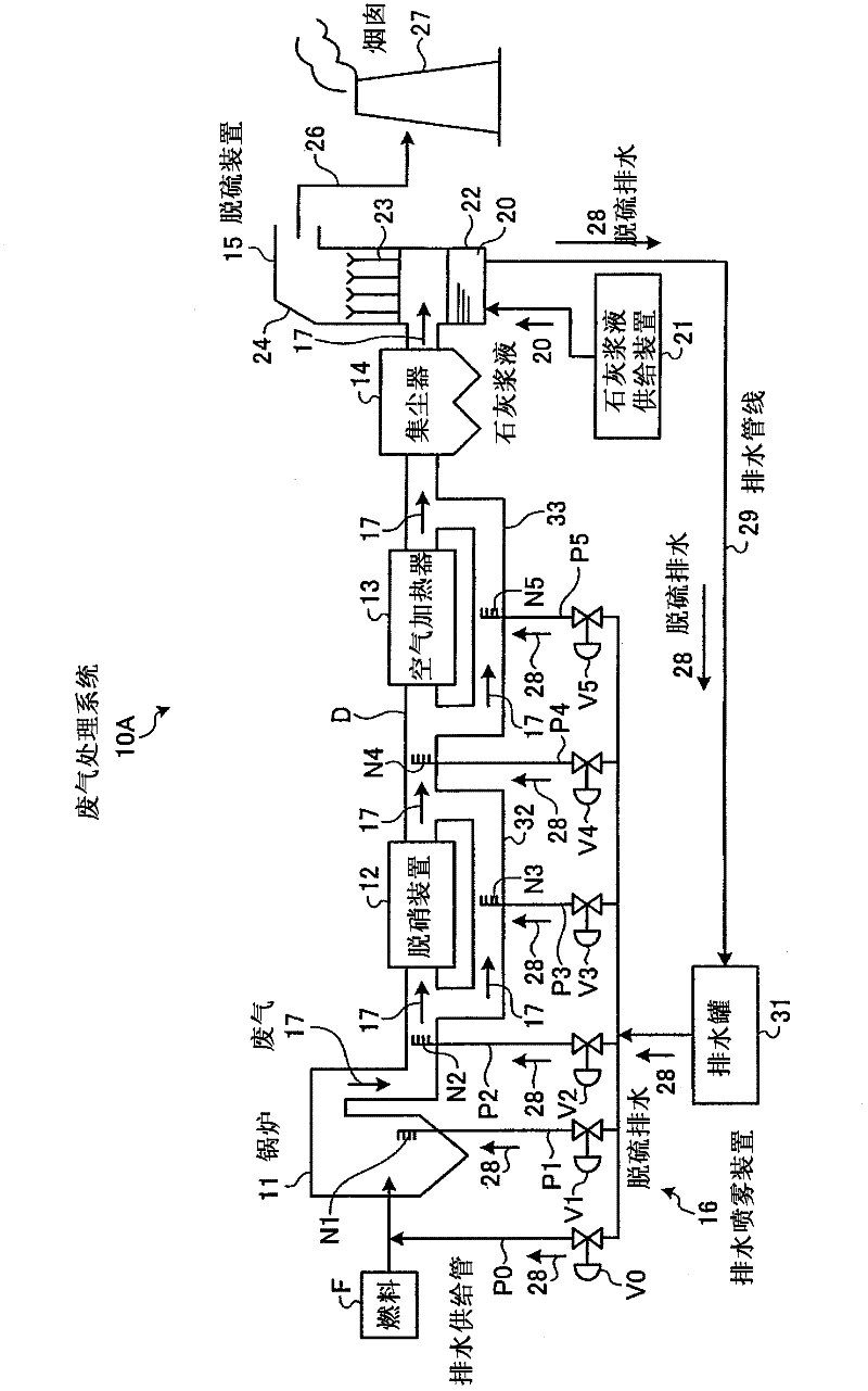
[0040] figure 1 It is a schematic structural diagram of the waste gas treatment system of Example 1. figure 1 The illustrated exhaust gas treatment system 10A converts nitrogen oxides (NO x ), sulfur oxides (SO x ), mercury (Hg) and other harmful substances removal device.

[0041] The exhaust gas treatment system 10A is configured to include: a denitrification device 12 for removing nitrogen oxides in the exhaust gas 17 from the boiler 11; an air heater 13 for recovering the heat of the exhaust gas 17 passing through the denitrification device 12; The dust collector 14 that removes the smoke and dust in the waste gas 17; the desulfurization device 15 that removes the sulfur oxides in the waste gas 17 after the smoke and dust is removed in a wet manner; and the desulfurization wastewater 28 discharged from the desulfurization device 15 is supplied to The route for supplying the fuel F to the boiler 11 , the furnace interior of the boiler 11 , and the drainage spraying devic...

Embodiment 2

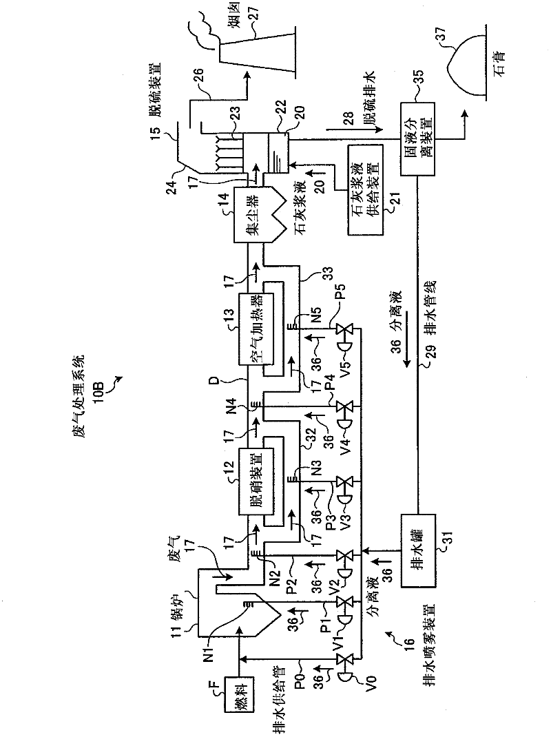
[0074] Next, the exhaust gas treatment system of Example 2 will be described. It should be noted that the same reference numerals are assigned to the same configurations as in the first embodiment described above, and description thereof will be omitted. figure 2 It is a schematic configuration diagram of the exhaust gas treatment system 10B of the second embodiment. In the above-mentioned embodiment 1, the desulfurization wastewater 28 discharged from the desulfurization device 15 is not treated, and the desulfurization wastewater 28 is directly atomized and sprayed into the exhaust gas 17 inside the boiler 11 and the flue D, but in the embodiment 2 In the wastewater treatment system 10B, a solid-liquid separation device 35 is installed in the middle of the drainage line 29, and the desulfurization wastewater 28 from the desulfurization device 15 is separated into solid and liquid by the solid-liquid separator 35, and the separated liquid (treated wastewater) is supplied to ...

Embodiment 3

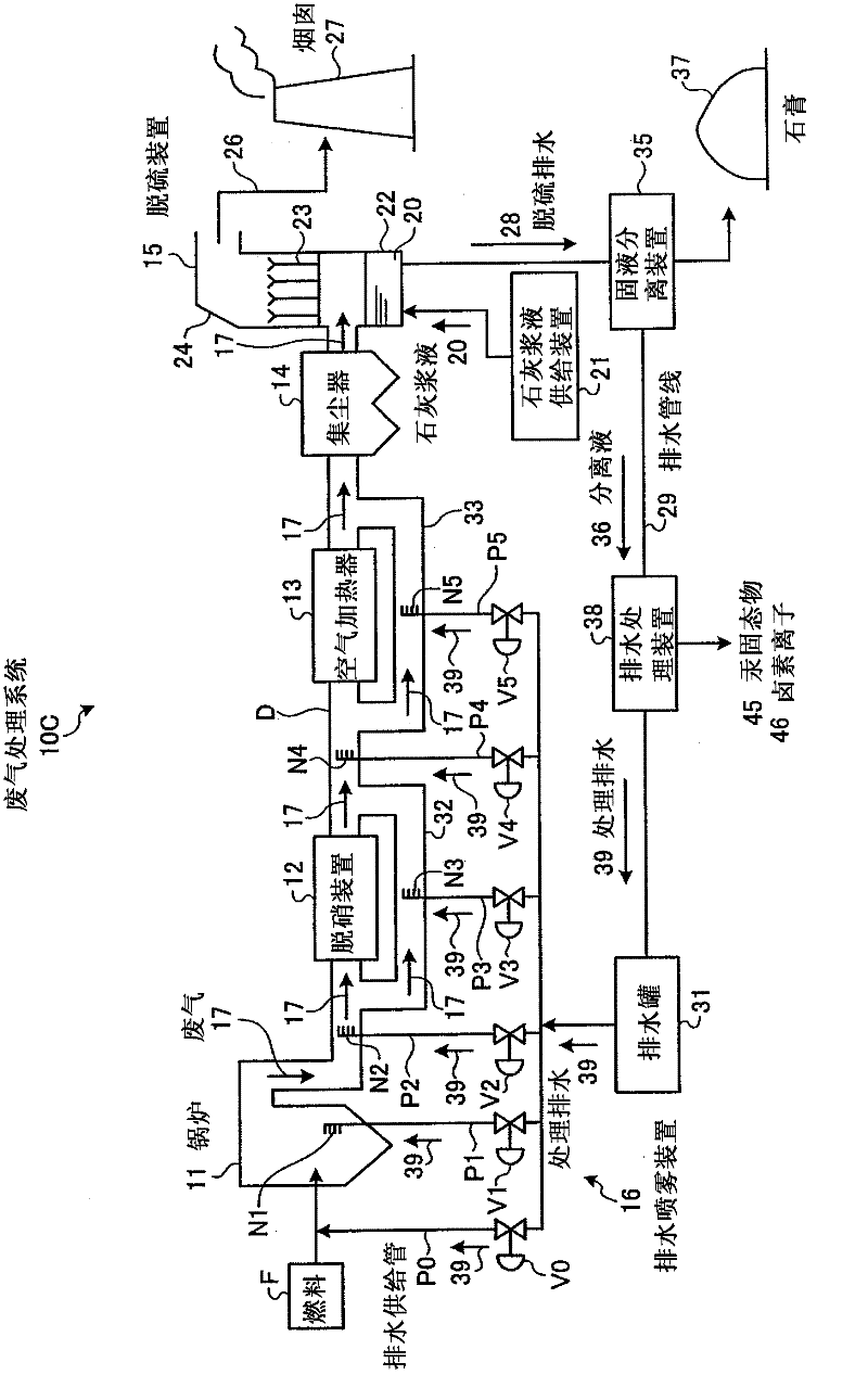
[0078] Next, the exhaust gas treatment system of Example 3 will be described. In addition, the same code|symbol is attached|subjected to the same structure as the said Example 1, 2, and the description is abbreviate|omitted. image 3 It is a schematic structural diagram of 10 C of waste gas treatment systems of Example 3. In the above-mentioned embodiment 2, the solid-liquid separation device 35 is installed in the middle of the drainage line 29, and the desulfurization wastewater 28 from the desulfurization device 15 is separated into solid and liquid by the solid-liquid separation device 35, and the separated liquid 36 is supplied to the The path through which the boiler 11 supplies the fuel F, the inside of the furnace of the boiler 11, the inside of the flue D, and the inside of the bypass pipes 32 and 33. There is a waste water treatment device 38 through which harmful substances and suspended solids in the separation liquid 36 are removed, and then the treated waste wat...


PUM


Abstract

Disclosed is an exhaust gas treatment system (10A) which is provided with a boiler (11) for burning fuel, an air heater (13) for collecting the heat of the exhaust gas (17) from the boiler (11), and a desulfurization unit (15) which removes, by means of an absorption liquid, the sulfur oxide contained in the exhaust gas (17) after the heat thereof was collected, wherein a wastewater supplying means (P0 to P5), which supplies the desulfurization wastewater (28) that is discharged from the desulfurization unit (15), is disposed on at least one of the following locations: a path for supplying fuel to the boiler (11), inside the furnace of the boiler (11), or inside the smoke path between the boiler (11) and the air heater (13). As a consequence of having the abovementioned configuration, the amount of desulfurization wastewater, that is returned to the smoke path per unit time, can be increased compared to the prior art without having to increase the size of the entire exhaust gas treatment system.

Description

technical field [0001] The present invention relates to a waste gas treatment system and method for treating waste gas discharged from a boiler. Background technique [0002] Conventionally, there is known an exhaust gas treatment system for treating exhaust gas discharged from boilers installed in thermal power generation facilities and the like. The exhaust gas treatment system is equipped with: a denitrification device for removing nitrogen oxides from the exhaust gas from the boiler; an air heater for recovering the heat of the exhaust gas passing through the denitrification device; a dust collector for removing smoke and dust in the exhaust gas after heat recovery; And a desulfurization device for removing sulfur oxides in the exhaust gas after dust removal. As a desulfurization device, a wet type desulfurization device that removes sulfur oxides in the exhaust gas by bringing a lime absorbent or the like into gas-liquid contact with the exhaust gas is generally used. ...

Claims


Application Information

Patent Timeline
Patent Type & Authority Applications(China)
IPC IPC(8): B01D53/50B01D53/77C02F1/04C02F1/28C02F1/44C02F1/469C02F1/52C02F1/58C02F1/62C02F1/74C02F11/00
CPCC02F1/385B01D53/50C02F1/683C02F1/001C02F1/441B01D2257/602C02F2101/108C02F2101/14C02F1/5236B01D53/1481C02F9/00C02F2103/18B01D2258/0283B01D2257/404C02F2101/106C02F2101/12B01D2251/2062B01D2257/20B01D53/75C02F1/4693B01D2251/2067B01D2257/302B01D53/8625B01D2251/404B01D2251/206C02F2101/20Y02A50/20B01D53/14B01D53/77C02F1/58
Inventor 鹈饲展行村上盛纪冲野进长安立人香川晴治
Owner MITSUBISHI HEAVY IND LTD
Why Eureka
Try Eureka