Drum microfiltration machine

A technology of microfiltration machine and drum, which is applied in the direction of filtration separation, mobile filter element filter, separation method, etc., can solve the problems of complex structure, large occupied area, increased failure rate, etc., and achieve compact overall structure and small occupied area. The effect of small size and low equipment cost

Active Publication Date: 2012-07-25
HUATIAN ENG & TECH CORP MCC
View PDF5 Cites 14 Cited by
  • Summary
  • Abstract
  • Description
  • Claims
  • Application Information

AI Technical Summary

Problems solved by technology

[0002] At present, the rotary disc microfilters generally have complex structures, and installation, maintenance, and maintenance are not easy, resulting in unnecessary waste. It has the following defects: 1. Install 16 to 20 turntables on the rotary disc microfilter, and each turntable is divided into 6 pieces. ~8 pieces, the structure is complicated, and the installation of the filters on both sides of each small turntable is troublesome, and there are many consumables, and the corresponding cost is also high; 2. Each turntable microfiltration machine needs to be equipped with several adsorption devices, flushing devices and Several electronic control devices, as the amount of water to be treated increases, the number of these corresponding devices will increase exponentially, so the failure rate will increase accordingly; 3. The filter screen of the rotary disc microfilter is easy to be blocked during use, and high-pressure flushing needs to be started frequently Or adsorption device, to shorten the interval time between high-pressure flushing or adsorption of intercepted matter to ensure the cleanliness of the filter screen, so as to ensure the flow rate; 4. The rotary disc microfilter occupies a large area

Method used


Image

  • Drum microfiltration machine
  • Drum microfiltration machine
  • Drum microfiltration machine

Examples


Embodiment Construction

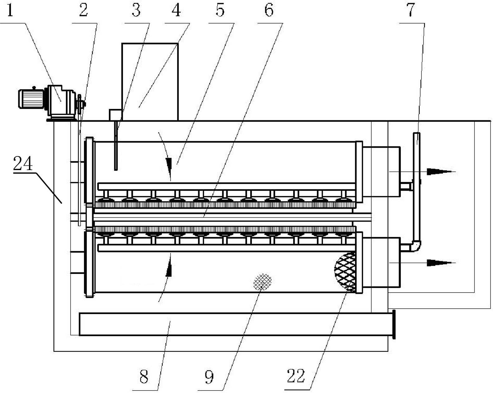
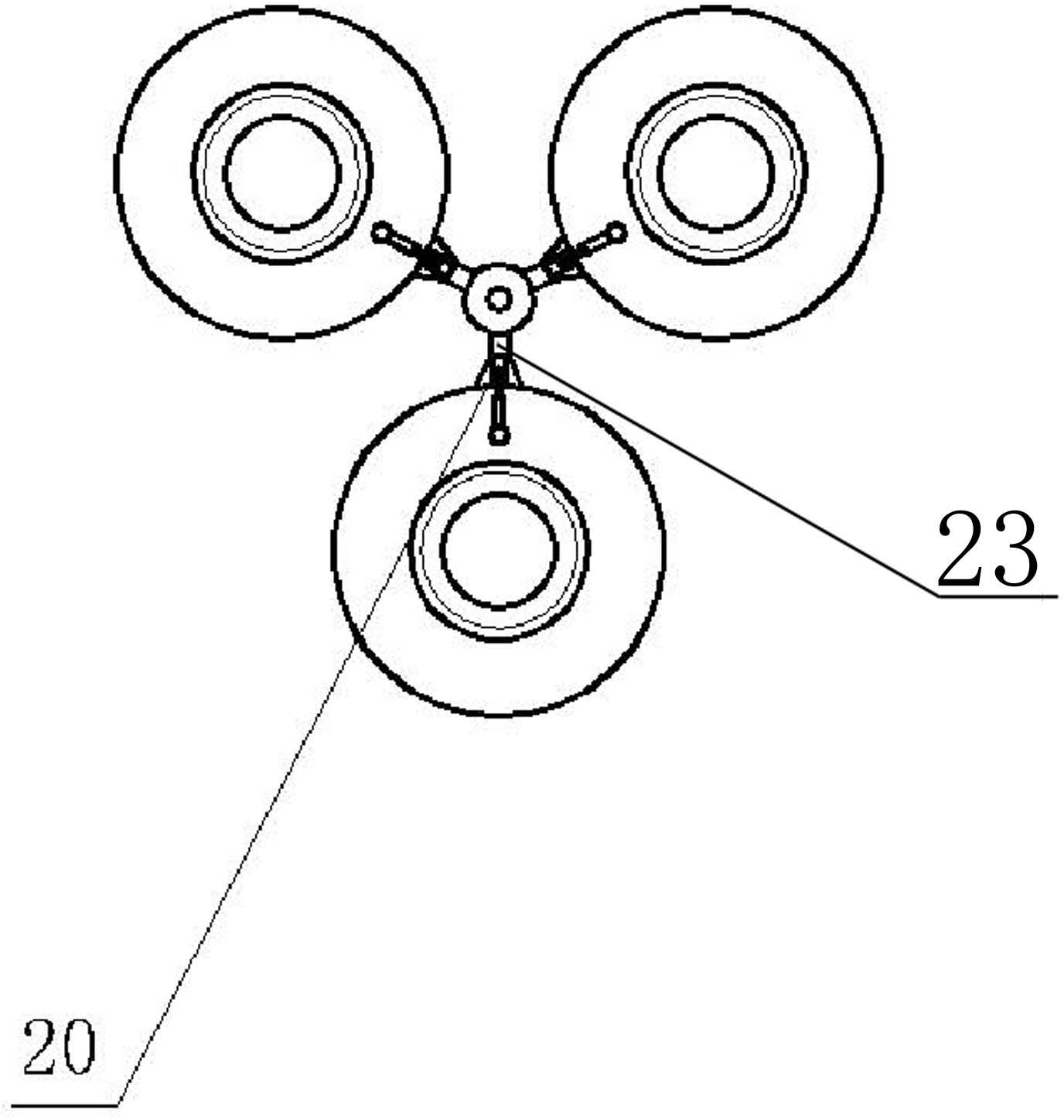
[0014] exist figure 1 and figure 2 , the present invention is a kind of drum microfilter, when the microfilter adopts external water inlet, it mainly comprises that the microfilter cartridge assembly is arranged horizontally, the microfilter cartridge assembly is located in the filter sedimentation tank 24, and the top of the filter sedimentation tank 24 is provided with There is a driving motor 1, and an electric control system 4 is arranged on the top of the filtration sedimentation tank 24, and the input end of the electric control system 4 is connected with a liquid level monitoring device 3, and the liquid level monitoring device 3 extends into the filtration sedimentation tank 24, and the electric control system The output end of 4 is connected with drive motor 1, and described micro-filter cartridge assembly mainly comprises functional shaft 6 and filter drum group 5, and the cylinder body of each drum of filter drum group 5 is support net 22, and the support net 22 su...


PUM


Abstract

The invention discloses a drum microfiltration machine. A microfiltration drum component of the drum microfiltration machine is located in a filtering sedimentation tank (24), a driving motor (1) is arranged at the top of the filtering sedimentation tank (24), the microfiltration drum component mainly comprises a functional shaft (6) and a filtering drum group (5), a drum body of each drum of the filtering drum group (5) is a supporting net (22), the functional shaft (6) is fixed at the center of the filtering drum group (5), the drums of the filtering drum group surround the functional shaft (6), a transmission system (2) is arranged between the driving motor (6) and the filtering drum group (5), the functional shaft (6) is hollow, water drainage components distributed between the functional shaft (6) and the filtering drum group (5) are arranged on the functional shaft (6) and are opposite to the filtering drum group (5), a high-pressure water inlet/outlet tube (7) is arranged at the other end of the functional shaft (6) and is communicated with the functional shaft (6), and a slag discharge tube (8) is disposed at the bottom of the microfiltration drum component.

Description

technical field [0001] The invention relates to a drum microfilter. Background technique [0002] At present, the rotary disc microfilters generally have complex structures, and installation, maintenance, and maintenance are not easy, resulting in unnecessary waste. It has the following defects: 1. Install 16 to 20 turntables on the rotary disc microfilter, and each turntable is divided into 6 pieces. ~8 pieces, the structure is complicated, and the installation of the filters on both sides of each small turntable is troublesome, and there are many consumables, and the corresponding cost is also high; 2. Each turntable microfiltration machine needs to be equipped with several adsorption devices, flushing devices and Several electronic control devices, as the amount of water to be treated increases, the number of these corresponding devices will increase exponentially, so the failure rate will increase accordingly; 3. The filter screen of the rotary disc microfilter is easy t...

Claims


Application Information

Patent Timeline
Patent Type & Authority Applications(China)
IPC IPC(8): B01D33/06B01D33/37B01D33/44
Inventor 张鑫珩王月萍程玉娟吴天福成兴龙
Owner HUATIAN ENG & TECH CORP MCC
Why Eureka
Try Eureka