Industrial robot

An industrial robot and horizontal rotation technology, which is applied in the direction of manipulators, manufacturing tools, mechanical equipment, etc., can solve the problems of time-consuming assembly, weight of the balance device, and more parts, so as to ensure the strength of the arm and the effect of longer stroke

Inactive Publication Date: 2012-07-25
NACHI-FUJIKOSHI
View PDF9 Cites 12 Cited by
  • Summary
  • Abstract
  • Description
  • Claims
  • Application Information

AI Technical Summary

Problems solved by technology

[0004] However, in the devices of Patent Documents 1 and 2, in order to obtain a large generating force, there is a problem that the spring-loaded housing becomes thicker and longer, and there is a problem that if the balance device is installed on the side of the arm, the width of the robot will be reduced. If the size becomes larger, if the balance device is installed behind the arm, the rotation interference radius at the rear of the robot will become larger
In addition, there is a problem that not only a plurality of springs are used, but also many parts are used, so not only the weight of the balancer is increased, but also it takes time to assemble, and the cost increases
[0015] However, the device of Patent Document 6 has a problem in that the balance device is arranged between the pair of arm bodies, so that it interferes with the arm rotation axis and can only rotate forward.
Therefore, it is only necessary to set the cantilever as in Patent Document 1, but at this time, the strength of the arm is lowered.
In addition, there is a problem that since the tip of the rod is arranged below the frame, it also interferes with the frame

Method used


Image

  • Industrial robot
  • Industrial robot
  • Industrial robot

Examples


Embodiment Construction

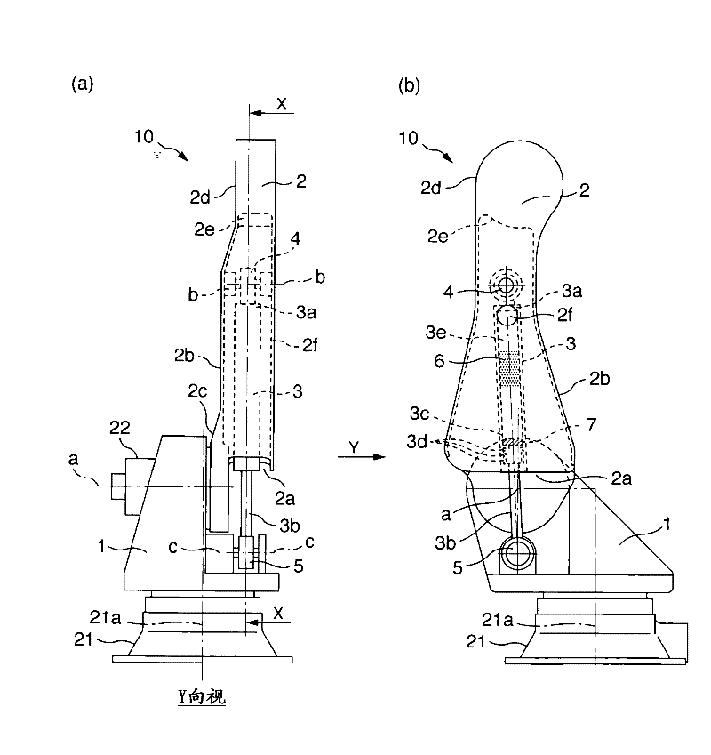
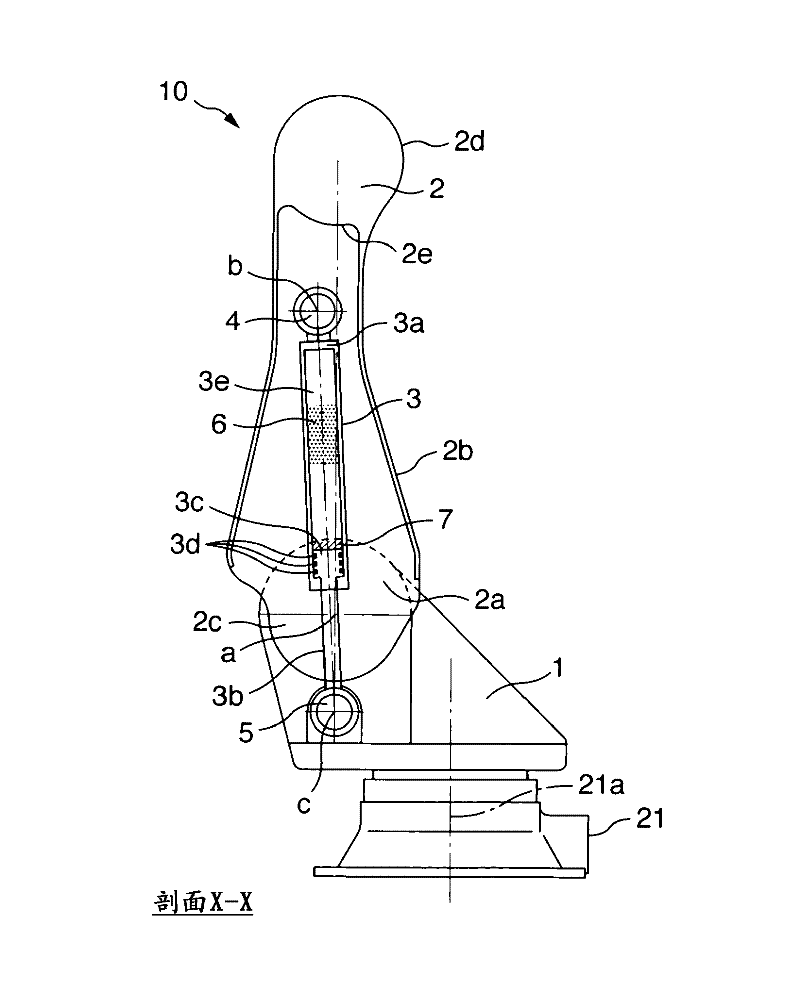
[0032] Embodiments of the present invention will be described with reference to the drawings. figure 1 (b) is a partial external view showing an industrial robot according to an embodiment of the present invention, figure 1(a) is figure 1 (b) Y-direction view, figure 2 yes means figure 1 (a) Partial sectional view of the X-X line section. Such as figure 1 , figure 2 As shown, the industrial robot 10 of the present invention has a frame 1 rotatable around a rotation axis 21a of a base 21, an arm 2 freely supported around a horizontal rotation axis a horizontally arranged on the frame (tilted rotation) and Balancing device 3 for lightening the load on the arm. The arm 2 is further provided with a second arm and a wrist (not shown) to constitute a multi-joint industrial robot, which is the same as conventional ones, and thus description thereof will be omitted.

[0033] The arm 2 is provided with a base portion 2c freely rotatable in a cantilever state and supported...


PUM


Abstract

An industrial robot 10 comprises an arm 2 which includes a proximal portion rotatably supported on a horizontal rotation shaft of a frame 1 in a cantilever state, a cylindrical case portion formed from the proximal portion side to a distal end of the arm to have an opening portion on the proximal portion side, and an arm distal end portion. The industrial robot also comprises a balancer device which includes a rod 3b , and a cylinder 3a in which the rod 3b is reciprocated. An engagement portion at a distal end of the rod, and a rear end 5 of the cylinder are rotatably supported between a pair of first support portions c of the frame, and between a pair of second support portions b inside the cylindrical case portion, respectively, so that the cylindrical case portion and the balancer device do not interfere with each other in an extent of rotation of the arm.

Description

technical field [0001] The present invention relates to an industrial robot having a balancing device for reducing the load on a motor and a reducer acting on a drive arm. Background technique [0002] In order to maintain the mass of the arm and the mass of the end effector attached to the tip of the robot using only the power of the motor, a large-capacity motor and a reducer are required. In particular, the moment load due to gravity increases as the shaft goes toward the root, so there is a problem that a large-capacity motor and a reducer are required. [0003] Therefore, in Patent Document 1, it is disclosed that a spring-type balancer is attached to the side of the arm, and one end is supported above the arm rotation shaft and the other end is supported on the arm side. In addition, Patent Document 2's Figure 4 , Figure 5 discloses a spring-type balancing device installed behind the arm. In addition, Patent Document 3 discloses a balance device formed of a hydrauli...

Claims


Application Information

Patent Timeline
Patent Type & Authority Applications(China)
IPC IPC(8): B25J19/00B25J18/00
CPCB25J19/0012Y10T74/20305
Inventor 宫本秀人
Owner NACHI-FUJIKOSHI
Why Eureka
Try Eureka