
Turbine engine driven fracturing pump truck

A technology of turbine engine and fracturing pump truck, which is applied to motor vehicles, auxiliary drive devices, and vehicles used for freight transportation, etc., can solve the problems of increasing the total mass of vehicles, long research and development cycle, and reducing mileage, so as to reduce land acquisition and transportation costs. The effect of working area, saving manpower and material resources, and improving output power

Active Publication Date: 2016-01-13
LIAONING HUAFU PETROLEUM HIGH TECH
View PDF7 Cites 0 Cited by
  • Summary
  • Abstract
  • Description
  • Claims
  • Application Information

AI Technical Summary

Problems solved by technology

[0004] However, the above two types of technical solutions all have certain defects. It is costly to set up a shock absorber system for engineering vehicles or fracturing pumps, and special maintenance of the shock absorber system is required in the later stage, and the total mass of the vehicle is increased. Engineering vehicles for field work will undoubtedly reduce the mileage
[0005] Improving the vibration source itself, that is, the internal structure of the fracturing pump, is a fundamental solution, but the required research and development cycle is long, and existing products cannot be used

Method used


Image

  • Turbine engine driven fracturing pump truck
  • Turbine engine driven fracturing pump truck
  • Turbine engine driven fracturing pump truck

Examples


Embodiment 1

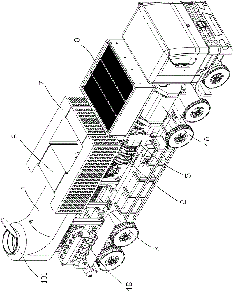
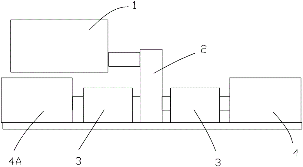
[0034] Embodiment 1 has two fracturing pumps installed horizontally opposite each other, such as figure 2 Shown:

[0035] For the convenience of expression, the direction of the chassis towards the front of the vehicle is called the front, and the direction of the chassis towards the rear of the vehicle is called the rear.

[0036] In order to effectively utilize the space of the automobile chassis, preferably, a fracturing pump is respectively installed at the front of the automobile chassis, and a reduction box 2 is installed at the middle of the automobile chassis. The reduction box 2 has two output shafts located on both sides of the reduction box, that is, the extension directions of the two output shafts are opposite. The other output shaft faces the front of the car and is connected with another fracturing pump I4A fixed on the front of the car chassis.

[0037] Furthermore, since the turbine engine has the advantages of small size and light weight, in this embodimen...

Embodiment 2

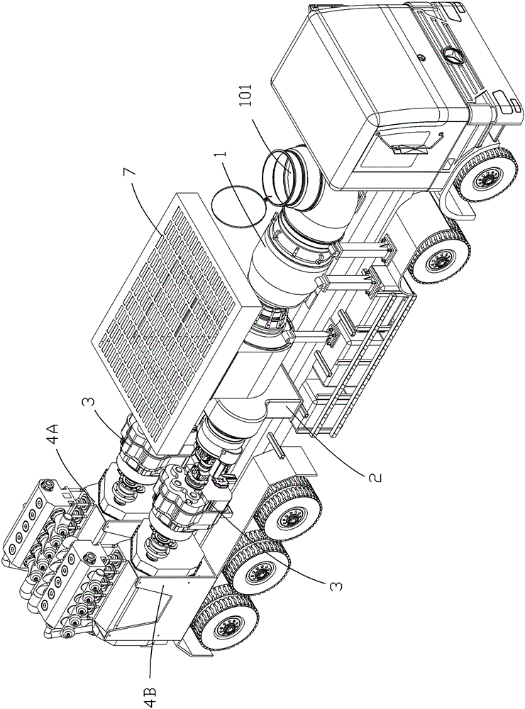
[0039] Embodiment 2 has two fracturing pumps centrally installed at the rear of the automobile chassis, such as figure 2 and Figure 4 Shown:

[0040] The turbine engine 1 is fixedly mounted on the front part of the chassis of the car, which is different from the elevated turbine engine 1 in Embodiment 1, and the turbine engine 1 in this embodiment is directly fixed on the chassis of the car. The speed reducer 2 is arranged in the middle part of the chassis of the car, and the two fracturing pumps 4 are installed side by side at the rear of the chassis of the car, so that the center of the car body is moved back, the weight of the front axle of the car body is reduced, and the stability of the chassis of the car is improved. bridge passability.

[0041] The transmission shaft of the turbine engine 1 is connected to the input shaft of the reduction box 2 . The reduction box 2 has two output shafts, and the two output shafts are located on the same side of the reduction box ...


PUM


Abstract

The invention provides a fracturing pump truck driven by a turbine engine, which comprises an engine, a fracturing pump, pipelines and the like. A traditional large and heavy diesel engine is replaced by the turbine engine which is small in size, light in weight and high in power, the total output power of a single fracturing pump truck can be more than 4000hp under the requirements of limited integral vehicle weight. The fracturing pump truck driven by one turbine engine is equivalent to the fracturing pump truck driven by two traditional diesel engines, so that output power of unit operating area is improved, more labor and materials can be saved in transport and specific constriction operations of fracturing equipment, land requisition and operating area are reduced, and construction efficiency is improved. Further, the turbine engine can also use various gaseous and liquid fuels and is especially suitable for shale gas exploitation.

Description

technical field [0001] The invention relates to a fracturing vehicle, in particular to a fracturing pump vehicle powered by a turbine engine for a fracturing pump. Background technique [0002] Fracturing pump trucks, as engineering vehicles widely used in modern oil and shale gas exploitation, provide convenience for oil and shale gas exploitation, but there are still many areas for improvement: most of the current fracturing pump trucks The power units of all fracturing pumps are reciprocating diesel engines. Due to the power limitation of diesel engines, all fracturing pump trucks use a diesel engine to drive a fracturing pump. The disadvantage is that the displacement and pump pressure of the fracturing pump are insufficient. For fracturing pump trains that require multiple engines to drive fracturing pumps when high power and displacement are required, it is a huge waste of resources for expensive engines, and the manufacturing cost of fracturing pump trains is high. L...

Claims


Application Information

Patent Timeline
Patent Type & Authority Patents(China)
IPC IPC(8): B60P3/14B60K25/06
Inventor 朱丽君李贵海肖俊宏罗明英李利远刘忠臣
Owner LIAONING HUAFU PETROLEUM HIGH TECH
Learn More