
Suction band table

The technology of a suction chamber and a transfer table is applied in the field of the device of the printing press, which can solve the problems such as the reduction of the sheet holding force, and achieve the effect of improving the separation characteristics.

Active Publication Date: 2012-07-25
HEIDELBERGER DRUCKMASCHINEN AG
View PDF7 Cites 4 Cited by
  • Summary
  • Abstract
  • Description
  • Claims
  • Application Information

AI Technical Summary

Problems solved by technology

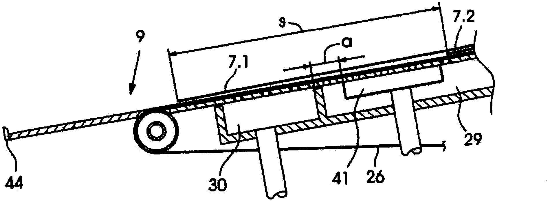
[0003] The problem with such a transfer table is that the respective second sheet of the sheet flow no longer rests on the transfer table completely with its scale length in the region of the second suction chamber during the orientation phase of the first sheet, resulting in a reduced holding force on the sheet

Method used


Image

  • Suction band table
  • Suction band table
  • Suction band table

Examples


Embodiment Construction

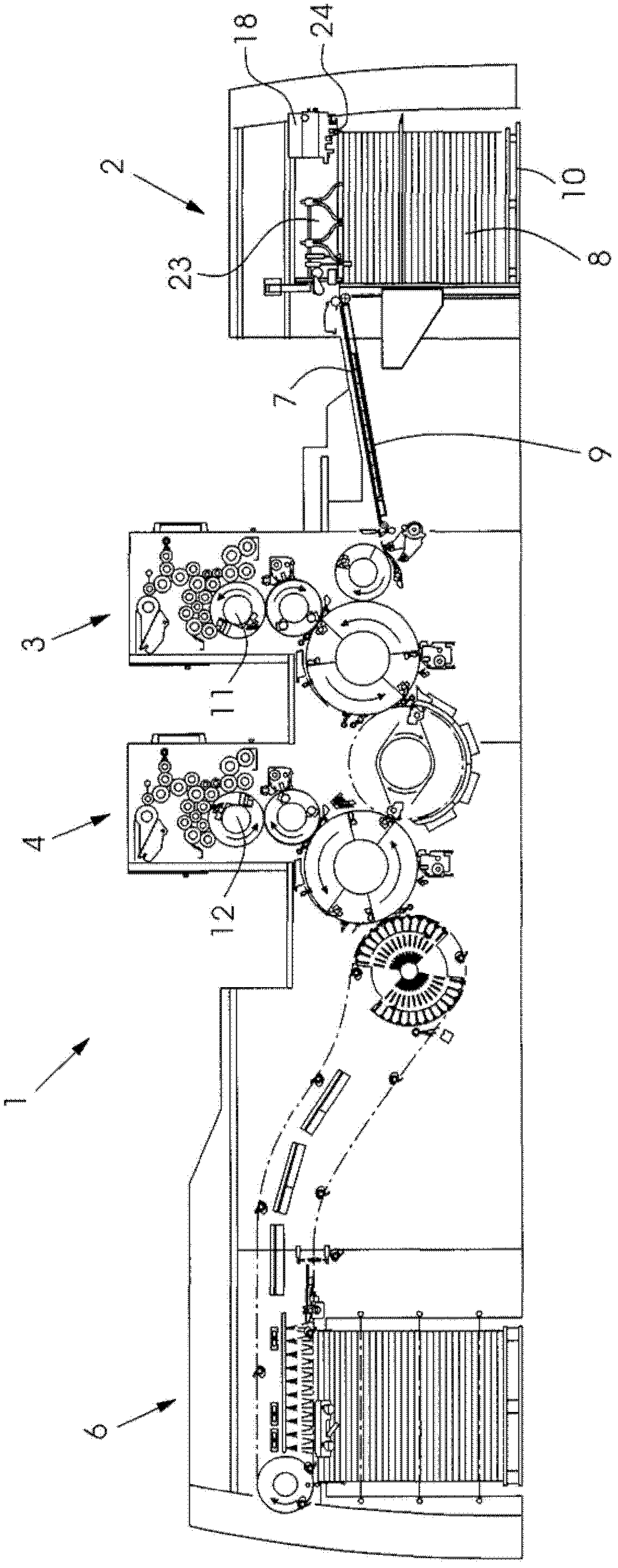
[0015] A machine for processing sheets 7 , such as a printing press 1 , has a feeder 2 , at least one printing unit 3 or 4 and a delivery 6 . The sheets 7 are removed from the sheet stack 8 and transported individually or in scales via a feed table 9 to the printing units 3 and 4 . The printing units each comprise a plate cylinder 11 , 12 in a known manner. The plate cylinders 11 and 12 each have means for fixing a flexographic printing plate. Furthermore, a device for semi-automatic or fully automatic changing of printing plates is assigned to each printing plate cylinder 11 , 12 .

[0016] The sheet stack 8 rests on a controllably raised and lowered main stack board 10 . The sheets 7 are removed from the top side of the sheet stack 8 by means of a so-called suction head 18 which essentially has a plurality of lifting and pulling suction devices for separating the sheets 7 . In addition, a blower device for blowing off the upper paper layer and a detection element for trac...


PUM


Abstract

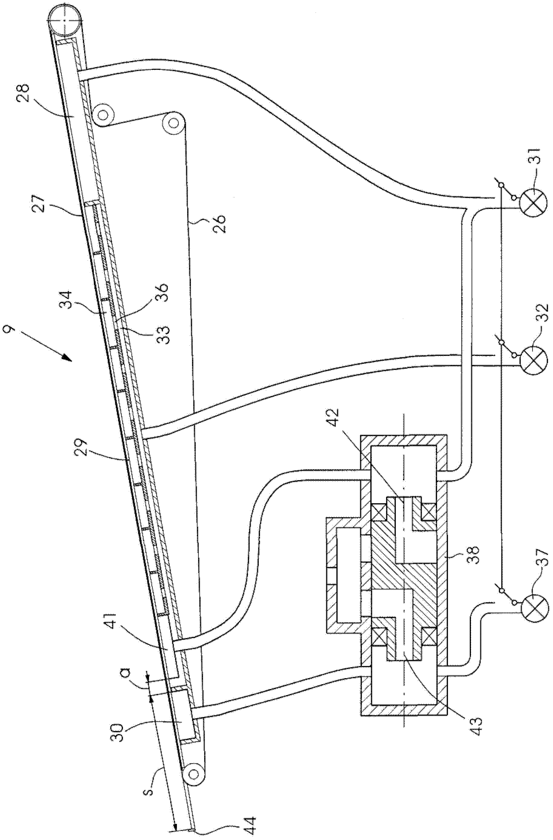
The invention refers to a suction band table, especially to a device used for transferring flake type pages to a page processor, especially to a printer. The device possesses a transferring table which is provided with at least a transferring belt which can be circled for driving and is permeable; the transferring table can be loaded with negative pressure by a plurality of front and back successively arranged suction chambers on the lower side of an upper belt sliding on the transferring table, wherein a last suction chamber arranged on the upstream of a page processing device can supply suction air having different pressure levels with beat of the page processing device. According to the invention, a suction chamber capable of loading different pressure levels is arranged facing the upstream of the last suction chamber on the page processing device.

Description

technical field [0001] The invention relates to a device for conveying a flaky sheet flow to a sheet processing machine, in particular a printing press, with a conveying table having at least one circularly driven and air-permeable conveyor belt, the conveying The underside of the upper belt, on which the belt can slide on the transfer table, is underpressured by a plurality of suction chambers arranged one behind the other. Background technique [0002] Such a device is known, for example, from DE 10213705 A1. Said document discloses a transfer table consisting of three suction chambers arranged one behind the other, wherein the first suction chamber can be acted upon with a high negative pressure, the second with a low negative pressure and the third The suction chamber can be acted upon with a high vacuum, wherein the vacuum of the third suction chamber is switched back and forth between high vacuum and low vacuum at the cycle time of the sheet processing machine. [00...

Claims


Application Information

Patent Timeline
Patent Type & Authority Applications(China)
IPC IPC(8): B65H5/22B65H5/24
CPCB65H2406/3221B65H11/005
Inventor H・埃丁格
Owner HEIDELBERGER DRUCKMASCHINEN AG
Learn More