Supercharge Your Innovation With Domain-Expert AI Agents!

Optical combustor probe system

An optical detector and photodetector technology, applied in optical radiation measurement, combustion chamber, controlled combustion, etc., can solve the problems of flame damage to upstream structures and damage

Inactive Publication Date: 2012-07-25
GENERAL ELECTRIC CO
View PDF4 Cites 0 Cited by
  • Summary
  • Abstract
  • Description
  • Claims
  • Application Information

AI Technical Summary

Problems solved by technology

If conditions supporting elevated lean flame velocities persist, the flame can encroach on upstream structures and cause damage due to increased heat loads or other causes

Method used


Image

  • Optical combustor probe system
  • Optical combustor probe system
  • Optical combustor probe system

Examples


Embodiment Construction

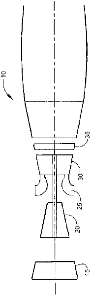
[0047] Referring now to the drawings, wherein like numerals refer to like elements throughout the several views, figure 1 A schematic diagram of a gas turbine engine 10 is shown. Gas turbine engine 10 may include a low pressure compressor 15 , a high pressure compressor 20 , a combustor 25 , a high pressure turbine 30 and a low pressure turbine 35 . The air flows through the low pressure compressor 15 and the compressed air is delivered to the high pressure compressor 20 . The highly compressed air is then delivered to the combustor 25 . Combustor 25 mixes a stream of compressed air with a stream of compressed fuel and ignites the mixture to produce a stream of combustion gases. The combustion gas flow is then delivered to turbines 30 , 35 . The flow of combustion gases drives turbines 30, 35 to produce mechanical work. Other configurations of other types of gas turbine engines 10 and components therein are also shown.

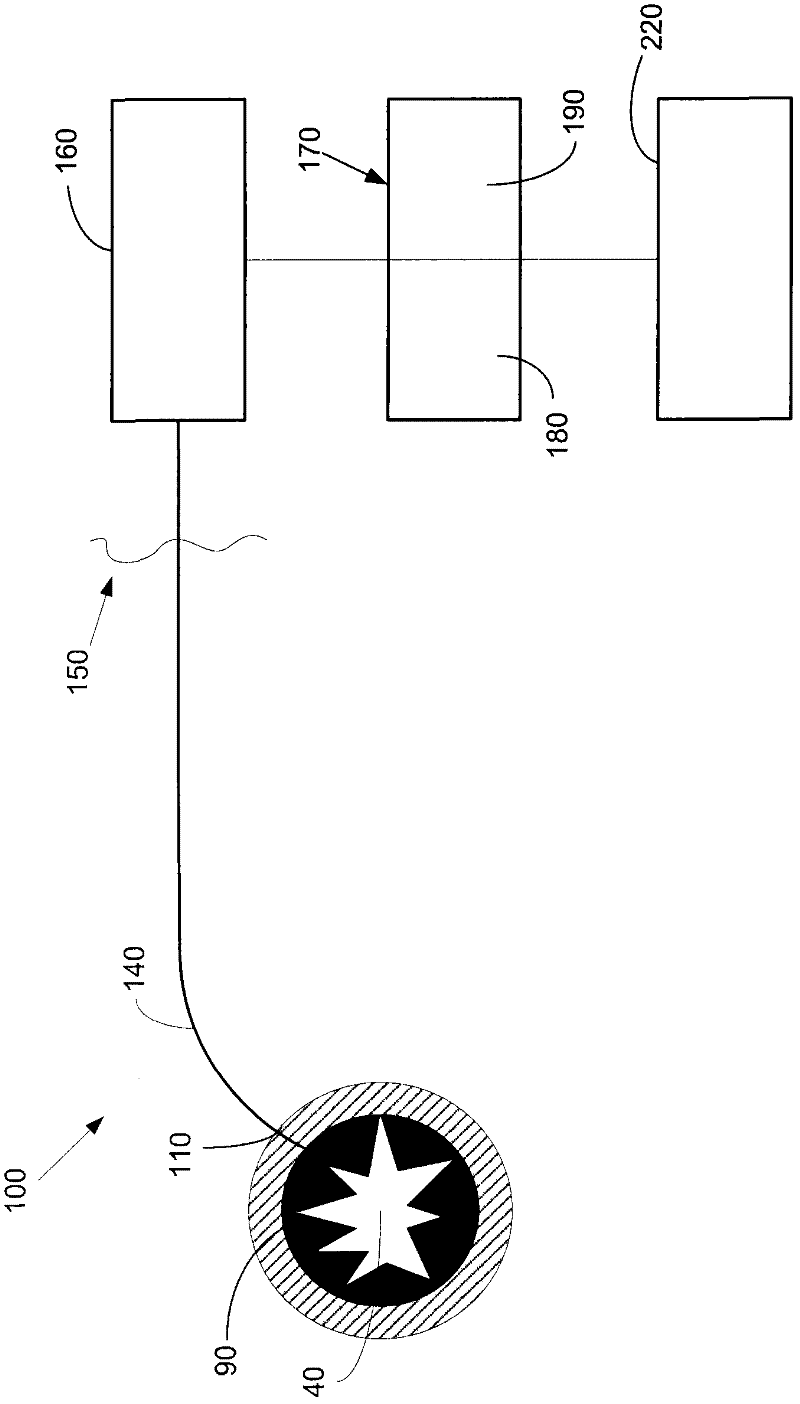
[0048] figure 2 is a partial side view of one exa...


PUM


Abstract

The present application provides an optical probe system (100) for use with a combustion flame (90) in a combustion chamber (40). The optical probe system (100) may include a number of optical probes (110) fixedly attached about the combustion chamber (40) and positioned such that the optical probes collect light generated by the combustion flame (90) in a field of view (210) of each of the optical probes. One or more components (150) external to the combustion chamber (40) may produce and analyze signals indicative of the light generated by the combustion flame (90) in the field of view (210) of each of the optical probes (110).

Description

technical field [0001] The present application relates generally to optical burner detector systems, and more particularly, to optical burner detector systems having a number of fiber optic detectors positioned around the perimeter of a combustion chamber to detect flame build-up and other types of combustion events. Background technique [0002] Certain types of known gas turbine combustors use lean premixed combustion to reduce emissions such as NO X (nitrogen oxides) and other gases. Such burners typically have a number of combustion devices attached to a single combustion chamber. During operation, fuel is injected through a number of fuel injectors and mixes with the swirling air flow to create a combustion flame. Lean premixed combustion results in lower flame temperatures and thus lower NO production due to lean stoichiometry X emissions of gases, etc. [0003] An aspect of the lean burn environment is that the flame speed can increase with increasing fuel concent...

Claims


Application Information

Patent Timeline
Patent Type & Authority Applications(China)
IPC IPC(8): G01J1/42F23N5/08F23R3/00
CPCG01N21/766F23N2029/16G01J3/0218F02D35/022F23N5/082F23N2229/16
Inventor S·维赫J·海恩斯K·麦芒努斯G·克诺特D·L·沃什伯恩
Owner GENERAL ELECTRIC CO
Features
  • R&D
  • Intellectual Property
  • Life Sciences
  • Materials
  • Tech Scout
  • Unparalleled Data Quality
  • Higher Quality Content
  • 60% Fewer Hallucinations
Learn More