Testing device for direct-current (DC) resistance of cable conductor

A technology for DC resistance testing and cable conductors, applied in measuring devices, measuring resistance/reactance/impedance, measuring electrical variables, etc., can solve problems such as large contact resistance, large current loss, data dispersion, and large volatility. Achieve the effect of reducing contact resistance, reducing cable cost and stabilizing product quality

Active Publication Date: 2012-07-25
ZHEJIANG CHENGUANG CABLE CO LTD
View PDF7 Cites 23 Cited by
  • Summary
  • Abstract
  • Description
  • Claims
  • Application Information

AI Technical Summary

Problems solved by technology

It can be seen from this figure that since the fan-shaped pre-twisted conductors are in contact with the left and right V-shaped clips 21 at both ends of the device, it is impossible to maintain a very uniform contact, and after the conductor is pre-twisted, the contact between the conductor and the V-shaped clips The situation has also changed. The contact between the conductor and the V-shaped clip is not the best, resulting in a large contact resistance, which causes the test current to not flow through each conductor monofilament evenly, resulting in a large loss of the actual current flowing, which eventually leads to the measurement. The resistance value obtained is larger than the actual conductor resistance value, and the dispersion and volatility of the data are large, which makes the test data of the conductor DC resistance untrue.

Method used


Image

  • Testing device for direct-current (DC) resistance of cable conductor
  • Testing device for direct-current (DC) resistance of cable conductor
  • Testing device for direct-current (DC) resistance of cable conductor

Examples


Embodiment Construction

[0018] The specific embodiments of the present invention will be further described below in conjunction with the accompanying drawings.

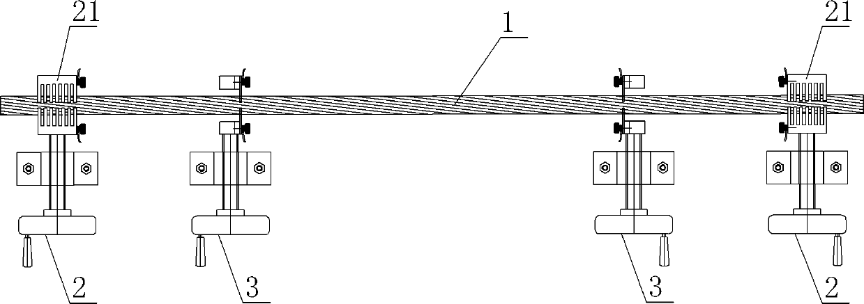
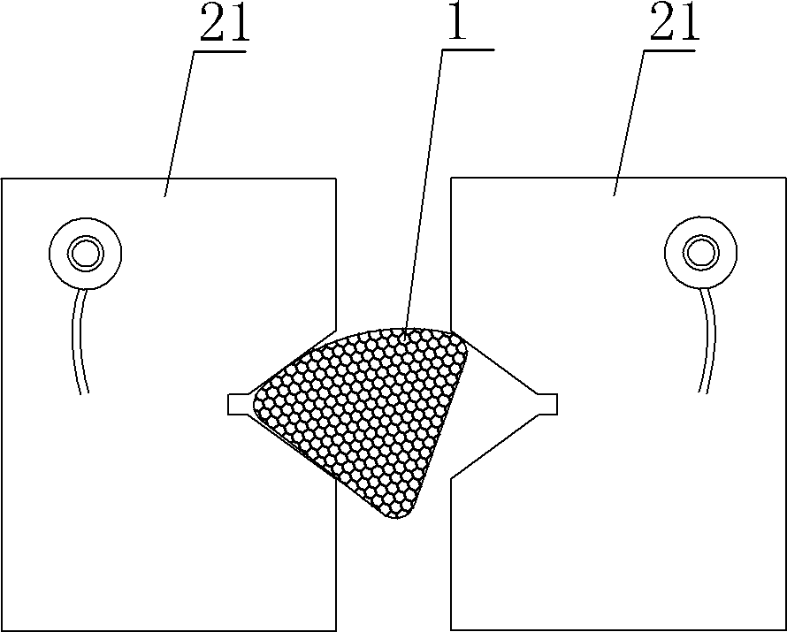
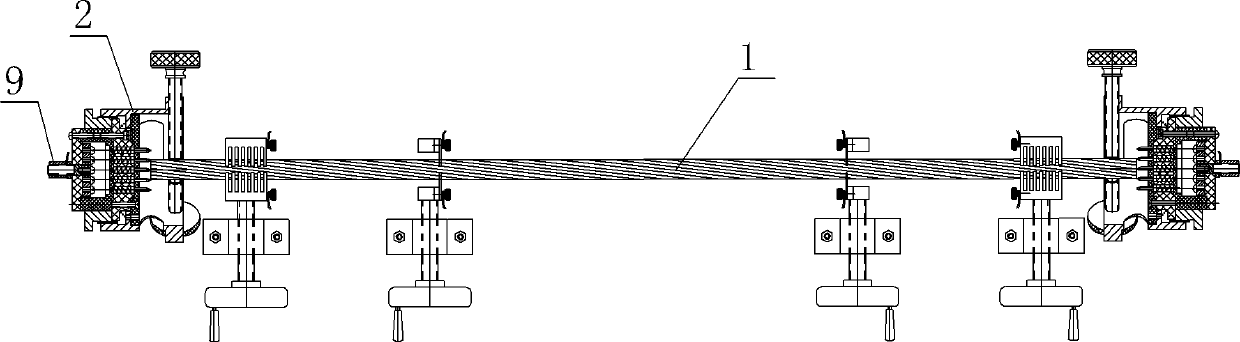
[0019] image 3 Shown is the cable conductor DC resistance testing device of the present invention, including two end face current input fixtures respectively arranged at the two ends of the testing device, as Figure 4 with Figure 5 As shown, the end face current input fixture includes a cap-shaped base 2, and the base 2 is provided with a clamping device and a current introduction device, and the current introduction device includes a 16 at the bottom of the base 2 The root tip 3 , the tip 3 has a needle-shaped tip, and the tip of the tip 3 protrudes from the inner side of the bottom of the base 2 . The top 3 is processed into a pointed needle shape from red copper, with a diameter of 3mm and a length of 12mm. These tips form a plurality of contact points to the pre-twisted conductor, which are uniformly arranged in the shape of a circ...


PUM


Abstract

The invention discloses a testing device for the direct-current (DC) resistance of a cable conductor. The testing device comprises two end-face current input fixtures which are respectively arranged at the two ends of the testing device, wherein each end-face current input fixture comprises a hat-shaped base, clamping devices and current importing devices are arranged on the bases, and each current importing device comprises a plurality of current importing terminals arranged at the bottom of the base. With the adoption of the technical scheme, the testing device for the DC resistance of the cable conductor has the advantages that: the DC resistance of the cable conductor is tested by adopting an end-face current input method, a testing current is enabled to directly enter the end faces of the conductor from the end-face current input fixtures through current leads, the current can evenly enter the conductor, and the testing current is truly guaranteed to flow through every monofilament to the maximum, so that the contact resistance between the conductor and the fixtures is reduced, the untruth of tested data on the DC resistance of the conductor is avoided, the quality of cable products is stabilized, and the cable cost is lowered.

Description

technical field [0001] The invention relates to a device for testing the DC resistance of a cable conductor. Background technique [0002] The current measurement of the DC resistance of cable conductors is a relatively mature test method. For conventional wires, circular stranded cores or conductors with compact circular structures, double-arm bridges or other resistance testing instruments are used to measure When using a four-terminal measuring fixture or four V-shaped test clamps to connect the tested sample, there is basically no large error in the DC resistance of the test cable conductor. For the structure of large-scale special-shaped conductors (sector-shaped or tile-shaped or compacted pre-twisted conductors), the correct measurement value is often not obtained by using this conventional DC resistance measurement method. Among them, the DC resistance test of large-scale compacted and pre-twisted conductors has a high probability of detection errors, the test data ...

Claims


Application Information

Patent Timeline
Patent Type & Authority Applications(China)
IPC IPC(8): G01R27/08
Inventor 金金元陈建平吴长顺杨士东
Owner ZHEJIANG CHENGUANG CABLE CO LTD
Why Eureka
Try Eureka