Multimode navigational radio frequency chip

A radio frequency chip and chip technology, applied in satellite radio beacon positioning systems, measuring devices, instruments, etc., can solve the problems that satellite navigation signals are susceptible to interference, cannot meet the needs of satellite navigation receivers, and destroy the integrity of satellite signals, etc., to achieve Improved anti-interference performance, low gain, and simple structure

Inactive Publication Date: 2013-09-04
天津中环微电子科技有限公司
View PDF5 Cites 0 Cited by
  • Summary
  • Abstract
  • Description
  • Claims
  • Application Information

AI Technical Summary

Problems solved by technology

Existing satellite navigation receivers rely on weak radio frequency satellite signals to work. The satellite navigation signal frequency is B1(1561.098±2.046)MHz, L1 frequency point: (1575.42±1.023)MHz, input receiving level:- 110dBm~-65dBm, the satellite navigation signal is easily interfered, destroying the integrity of the satellite signal, resulting in the reduction of navigation accuracy, so that the accurate positioning function cannot be realized
Satellite navigation receivers are usually equipped with a radio frequency front-end chip to amplify and process satellite radio frequency signals. The existing radio frequency front-end chips need to process satellite radio frequency signals of different satellite systems, which have problems such as complex structure, high power consumption, and poor consistency. Meeting the needs of satellite navigation receivers

Method used


Image

  • Multimode navigational radio frequency chip
  • Multimode navigational radio frequency chip
  • Multimode navigational radio frequency chip

Examples


Embodiment Construction

[0019] Embodiments of the present invention are described in further detail below in conjunction with the accompanying drawings:

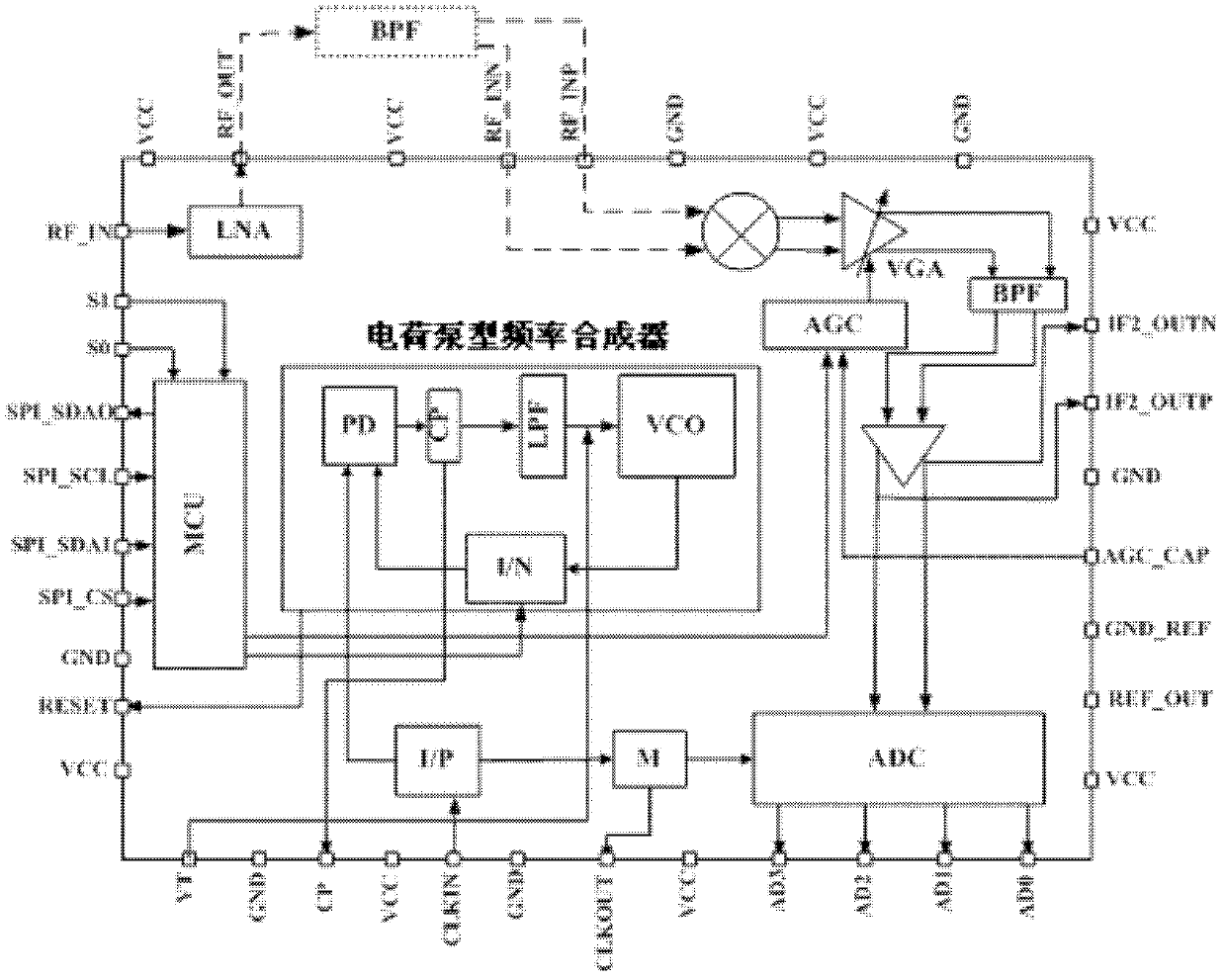
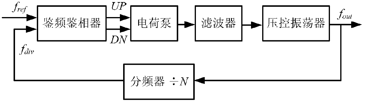
[0020] A multi-mode navigation radio frequency chip, such as figure 1 As shown, including MCU, charge pump frequency synthesizer, P counter, low noise amplifier (LNA), mixer, variable gain amplifier (VGA), on-chip bandpass filter (BPF), automatic gain controller ( AGC) and analog-to-digital converter (ADC). The MCU is respectively connected to the frequency selection signal S0 and S1 ports of the chip through two input interfaces, and the MCU is respectively connected to the input terminals of the charge pump type frequency synthesizer and the automatic gain controller (AGC) through two output interfaces to realize the charge pump. Type frequency synthesizer and automatic gain controller (AGC) control functions. The charge pump type frequency synthesizer is composed of a phase detector (PD), a charge pump (CP), a low-pass filter (LBF), a voltage-...


PUM


Abstract

The invention relates to a multimode navigational radio frequency chip which has the technical characteristics that a MCU (Microprogrammed Control Unit) are respectively connected with frequency selection signal ports S0 and S1 of the chip by two input interfaces; the MCU are respectively connected to a charge pump frequency synthesizer and one input end of an automatic gain controller by two output interfaces; the input end of the charge pump frequency synthesizer is connected with a P counter; a low noise amplifier is connected with an RF_IN port of the chip; the low noise amplifier is connected onto a variable gain amplifier by two output signals which are filtered and output by an off-chip band-pass filter through a frequency mixer; and the output end of the variable gain amplifier is output onto output ports AD0, AD1, AD2 and AD3 of the chip by an on-chip band-pass filter and an analog to digital converter. The multimode navigational radio frequency chip has reasonable design. The high-quality down-conversion scheme can be implemented for any one navigation signal under the frequency of B1 and at the frequency point of GPS (Global Positioning System) L1 in any environment and the satisfied bandwidth is obtained. The multimode navigational radio frequency chip has the characteristics of simple structure, stable performance, powerful functions, low cost and the like.

Description

technical field [0001] The invention belongs to the field of radio frequency integrated circuits, in particular to a multi-mode navigation radio frequency chip. Background technique [0002] At present, GPS-based satellite navigation systems and Beidou satellite navigation systems are more and more widely used. Users can use satellite navigation receivers to receive satellite signals and realize navigation functions. Existing satellite navigation receivers rely on weak radio frequency satellite signals to work. The satellite navigation signal frequency is B1(1561.098±2.046)MHz, L1 frequency point: (1575.42±1.023)MHz, input receiving level:- 110dBm~-65dBm, the satellite navigation signal is susceptible to interference, destroying the integrity of the satellite signal, resulting in the reduction of navigation accuracy, so that the accurate positioning function cannot be realized. Satellite navigation receivers usually set a radio frequency front-end chip to amplify and proces...

Claims


Application Information

Patent Timeline
Patent Type & Authority Patents(China)
IPC IPC(8): H04L27/00H04L27/144G01S19/32G01S19/36
Inventor 申研王博
Owner 天津中环微电子科技有限公司
Why Eureka
Try Eureka