Magnetic steel end fastening structure of permanent magnet motor rotor

A permanent magnet motor and end fastening technology, which is applied to the rotating parts of the magnetic circuit, the shape/style/structure of the magnetic circuit, etc., can solve the problems of inconvenient operation, no axial compression of the magnetic steel, complex process, etc. Achieve the effect of facilitating the manufacturing process and avoiding the loosening of the magnetic steel

Inactive Publication Date: 2012-07-25
SINOPAL (QINGDAO) ELECTRIC CO LTD
View PDF6 Cites 6 Cited by
  • Summary
  • Abstract
  • Description
  • Claims
  • Application Information

AI Technical Summary

Problems solved by technology

The magnetic steel of each pole is divided into n sections in the axial direction and inserted into the magnetic steel slot. Due to manufacturing errors, there is a certain deviation between the axial length of the magnetic steel slot and the sum of the axial lengths of the n sections of magnetic steel. Therefore, this fastening method has the advantages of The following problems: 1. If the last section of the magnetic steel at both ends of the rotor extends out of the magnetic steel slot too long in the axial direction, it will cause the end rigid pressure ring to be directly stressed on the magnetic steel and crush it; if the last section of the rotor at both ends If the axial direction of a piece of magnetic steel is too short and it is recessed into the magnetic steel groove, the rigid pressure ring is directly stressed on the iron core surface, and the magnetic steel is not axially compressed; 2. The total axial direction of the magnetic steel in the magnetic steel groove of each pole There is a deviation in the length, and it is impossible for the full circle pressure ring to be pressed together with the end faces of the magnetic steel of all poles at the same time; 3. Since the magnetic steel of the same pole needs to be installed before installing the next pole, it must Re-make the compression tooling on the top, and temporarily fix each pole. After all the magnetic steels of the poles are installed, remove the tooling and replace it with a full-circle pressure ring to press on the end faces of the magnetic steels of all poles.
The process is complicated, and the operation is very inconvenient, and it is likely to cause loosening of the magnetic steel that has been compressed in the groove and bonded with epoxy glue but not fully cured when the tooling is removed

Method used


Image

  • Magnetic steel end fastening structure of permanent magnet motor rotor
  • Magnetic steel end fastening structure of permanent magnet motor rotor
  • Magnetic steel end fastening structure of permanent magnet motor rotor

Examples


Embodiment Construction

[0016] The specific embodiments of the present invention will be further described below in conjunction with the drawings.

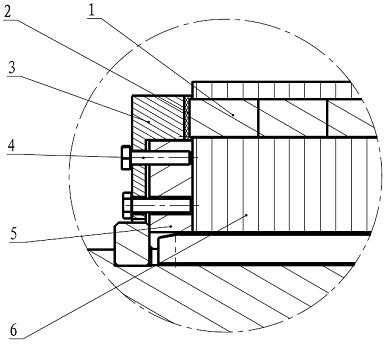
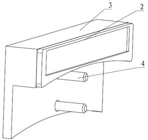
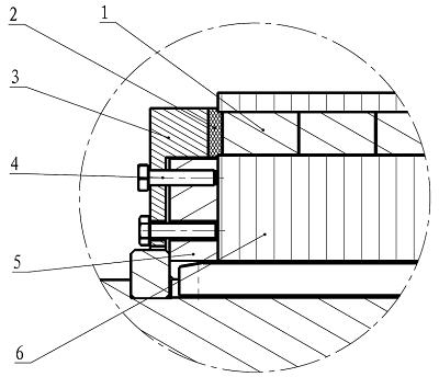
[0017] Such as figure 1 , image 3 As shown, the present invention is composed of magnetic steel 1, thermally expandable glass felt 2, stainless steel pressing plate 3, stainless steel fastener 4, rotor iron core pressing ring 5 and rotor iron core 6. The magnetic steel 1 (only one pole is shown in the figure) is inserted into the magnetic steel groove of the rotor iron core 6 in several sections in the axial direction, and the rotor iron core pressing ring 5 is pressed against the end surface of the rotor iron core 6. The stainless steel pressing plate 3 is pressed on the magnetic steel 1 and the rotor core pressing ring 5, and is fastened to the rotor iron core pressing ring 5 with stainless steel fasteners 4 (bolts).

[0018] The stainless steel pressure plate 3 is not directly pressed on the magnet 1, but a layer of flexible heat-expandable glass mat 2 is...


PUM


Abstract

The invention provides a magnetic steel end fastening structure of a permanent magnet motor rotor. The structure comprises magnetic steel, a thermal expansion glass felt, a stainless steel pressure plate, a stainless steel fastener, a rotor core pressure ring and a rotor core, wherein the magnetic steel is axially divided into multiple sections which are inserted into the magnetic steel slots of the rotor core; the rotor core pressure ring is compacted on the end surface of the rotor core; the stainless steel pressure plate is compacted on the magnetic steel and the rotor core pressure ring and connected with the rotor core pressure ring through the stainless steel fastener; and the thermal expansion glass felt is located between the stainless steel pressure plate and the magnetic steel. In the invention, the axial thickness is freely adjusted by use of the high expansion rate of the thermal expansion glass felt so as to realize flexible fixation of the magnetic steel and solve the problems caused by the manufacturing error. Moreover, since each pole is provided with an independent fastening device, the technological tool is not needed, the manufacturing process is facilitated, and the loosening of the magnetic steel caused by dismantling the tool is avoided.

Description

Technical field [0001] The invention relates to the field of permanent magnet motor rotors, in particular to a permanent magnet motor rotor built-in magnetic steel end axial fastening structure with novel structure, good performance and convenient installation. Background technique [0002] The existing axial fastening structure of the embedded magnet end of the permanent magnet motor generally uses a full-circle pressing ring made of stainless steel and other materials to simultaneously compress all the magnets of the pole number. Each pole of the magnetic steel is divided into n sections in the axial direction and inserted into the magnetic steel groove. Due to manufacturing errors, there is a certain deviation between the axial length of the magnetic steel groove and the sum of the axial length of the n sections of the magnetic steel. Therefore, this fastening method has The following problems: 1. If the last section of the magnet at both ends of the rotor protrudes out of the...

Claims


Application Information

Patent Timeline
Patent Type & Authority Applications(China)
IPC IPC(8): H02K1/28
Inventor 朱红燕周会军王成王裕峰杨菲黄森林郭强安康平陈恒峰
Owner SINOPAL (QINGDAO) ELECTRIC CO LTD
Why Eureka
Try Eureka