Signal line fixing structure of resolver

A technology of resolver and signal line, applied in the field of resolver, can solve the problems of damage, lengthy process requirements of the whole line procedure, and falling off of the extension lead 7, so as to reduce the demand of the whole line, ensure the reliability, and shorten the length. Effect

Inactive Publication Date: 2012-07-25
HIWIN MIKROSYST
View PDF4 Cites 3 Cited by
  • Summary
  • Abstract
  • Description
  • Claims
  • Application Information

AI Technical Summary

Problems solved by technology

[0004] Although the above-mentioned specific prior art can complete the electrical connection state between the stator coil and the outside, yet because it makes the fixed pin portion 2 be positioned in the limited space between the adjacent two tooth poles 5, when the stator When the number of tooth poles is large, even if the fixed pin portion 2 cannot be arranged in the narrow space between two adjacent tooth poles 5, moreover, since the stator coil 6 is finished winding, its wire ends are not connected with each other. The fixed pin portion 2 is located at the same position, therefore, the wire end of the coil must be connected to the fixed pin portion 2 via the extension lead 7, that is to say, the extension lead 7 must be fixed on the entire line process. The end side of the stator is further extended to connect with the fixed pin part 2. In this way, it will lead to the lengthy process requirements of the whole line program, and the high heat generated when the motor is running will also make it used for fixed extension in the whole line program. The insulating adhesive of the lead wire 7 falls off under the action of temperature, causing the originally fixed extension lead 7 to lose its position and shift, causing the extension lead 7 to fall off, rub, and cause damage

Method used


Image

  • Signal line fixing structure of resolver
  • Signal line fixing structure of resolver
  • Signal line fixing structure of resolver

Examples


Embodiment 1

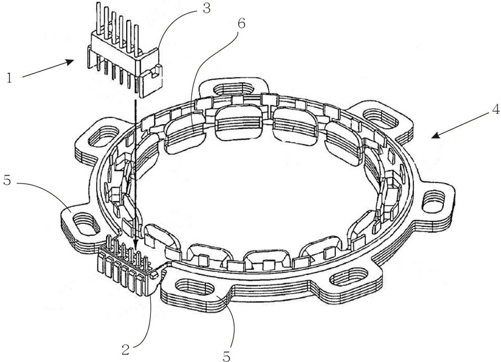
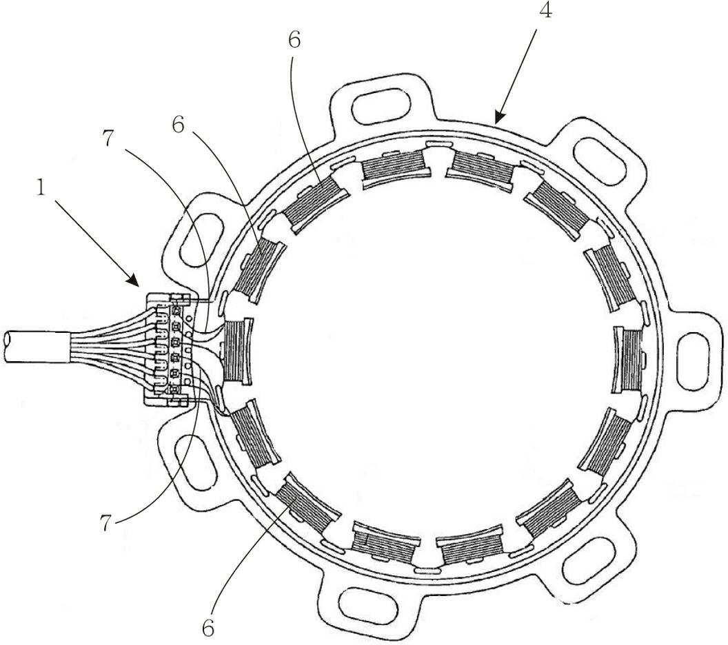
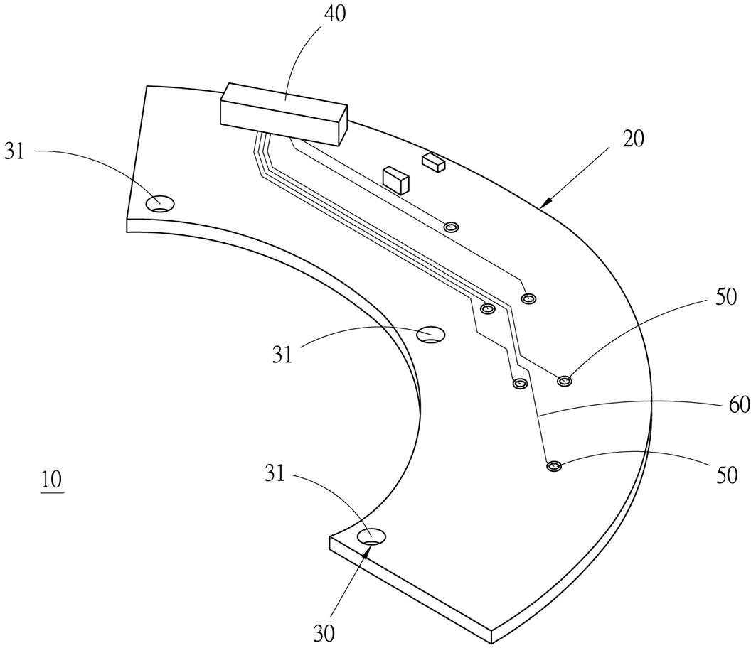
[0038] see Figure 3 to Figure 6 As shown, the signal line fixing structure 10 of the resolver provided in a preferred embodiment of the present invention is mainly composed of a circuit board 20, a fixing part 30, a combined terminal block 40, a plurality of connecting parts 50 and It is composed of a plurality of bridge circuits 60 .

[0039] The circuit board 20 is roughly in the shape of an arc plate, and is attached to the axial end surface 71 of a resolver stator 70 with one side plate surface 21, and its center of curvature corresponds to the axial coaxial direction of the stator 70, and The size of the circuit board 20 covers a plurality of coils 72 with winding ends on the stator 70 , so that each winding end is located within the projected range of one side of the circuit board 20 .

[0040] The fixing part 30 is used to combine the circuit board 20 on the axial end surface 71 of the stator, and has three fixing holes 31 respectively penetrated between the two side ...


PUM


Abstract

The invention provides a signal line fixing structure of a resolver. The signal line fixing structure is fixed on a shaft end of a stator of the resolver, and comprises the following components: a circuit board; a fixing part arranged on the circuit board and used for combining the circuit board on the end face of the shaft end of the stator; a terminal combination base arranged on the circuit board; multiple poroid connection parts respectively arranged on the circuit board in a penetration manner; and multiple bridge circuits, which are respectively located between one corresponding connection part and the terminal combination base, and used for bridging the corresponding connection part and the terminal combination base. The product disclosed by the invention can be suitable for the stator with less or more teeth, can greatly reduce the extending length of a lead, and can also avoid the situation where each bridge circuit is in short circuit with a stator coil or each wind-out end, thereby ensuring the reliability of the product; and the product disclosed by the invention can further integrate the electronic parts needed for the resolver on the circuit board, thereby realizing the effect of simplification of components.

Description

technical field [0001] The present invention relates to resolvers, in particular to a signal line fixing structure of resolvers. Background technique [0002] The resolver is used as a feedback device for feeding back the rotational position of the motor. It mainly uses the excitation coil of the stator to pass an excitation signal to generate a magnetic field interlinkage with the rotating rotor, and then the induction coil of the stator induces the magnetic field to output an induction signal. The formation of the upper coil is generally completed by winding the wire on the slot teeth on the stator. However, since the completed coil still needs to be electrically connected to the outside, the coil must pass through a set of coils after the winding is completed. Connecting members to form an electrical connection with the outside. [0003] And the existing technical content for assembling the electrical connection state between the coil and the outside, specifically, it is...

Claims


Application Information

Patent Timeline
Patent Type & Authority Applications(China)
IPC IPC(8): H02K3/50
Inventor 赖明志李奇录王之佑
Owner HIWIN MIKROSYST
Why Eureka
Try Eureka