
Power factor correction circuit

A power factor correction and power stage circuit technology, applied in the power supply field, can solve the problems of unfavorable circuit miniaturization and integration, increase system implementation cost, etc., and achieve the effect of reducing anti-electromagnetic interference

Active Publication Date: 2014-11-05
SILERGY SEMICON TECH (HANGZHOU) CO LTD
View PDF4 Cites 0 Cited by
  • Summary
  • Abstract
  • Description
  • Claims
  • Application Information

AI Technical Summary

Problems solved by technology

In order to realize the variability of switching frequency, frequency synthesis technology is usually used, such as using a separate dedicated chip for generating variable frequency, but the method of using a separate dedicated chip for generating variable frequency will also greatly increase the cost of system implementation, and will not Conducive to miniaturization and integration of circuits

Method used


Image

  • Power factor correction circuit
  • Power factor correction circuit
  • Power factor correction circuit

Examples


Embodiment Construction

[0052] Several preferred embodiments of the present invention will be described in detail below with reference to the accompanying drawings, but the present invention is not limited to these embodiments. The present invention covers any alternatives, modifications, equivalent methods and schemes made on the spirit and scope of the present invention. In order to provide the public with a thorough understanding of the present invention, specific details are set forth in the following preferred embodiments of the present invention, but those skilled in the art can fully understand the present invention without the description of these details.

[0053] The embodiment of the present invention discloses a power factor correction circuit. Through the inductor current sampling circuit, current modulation circuit and intermediate signal generation circuit in the power factor correction circuit, while realizing power factor correction, the frequency of the power switch tube is It is al...


PUM


Abstract

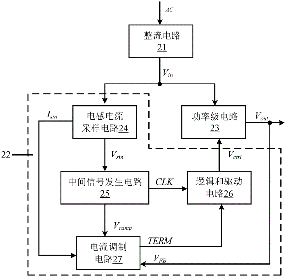
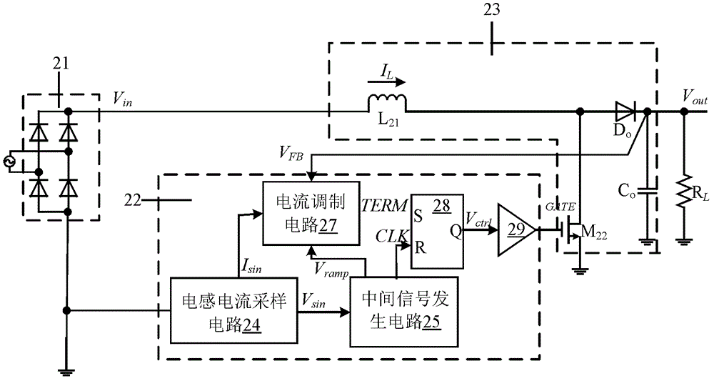
The present invention relates to a power factor correction circuit, that can include: an inductor current detector that generates a sampling voltage signal, and sinusoidal half-wave current and voltage signals based on the sampling voltage signal; a mediate signal generator generating slope voltage and clock signals in response to the sinusoidal half-wave voltage signal, where a frequency of each varies with the sinusoidal half-wave voltage signal; a current modulation circuit receiving the sinusoidal half-wave current signal and a voltage feedback signal representative of a power stage output voltage to generate a regulation signal that is compared against the slope voltage signal to generate a modulation signal; and a logic / driving circuit receiving the modulation and clock signals, and generating a controlling signal that controls a power switch with variable frequency to maintain the inductor current in phase with the sinusoidal half-wave voltage signal and the power stage output voltage constant.

Description

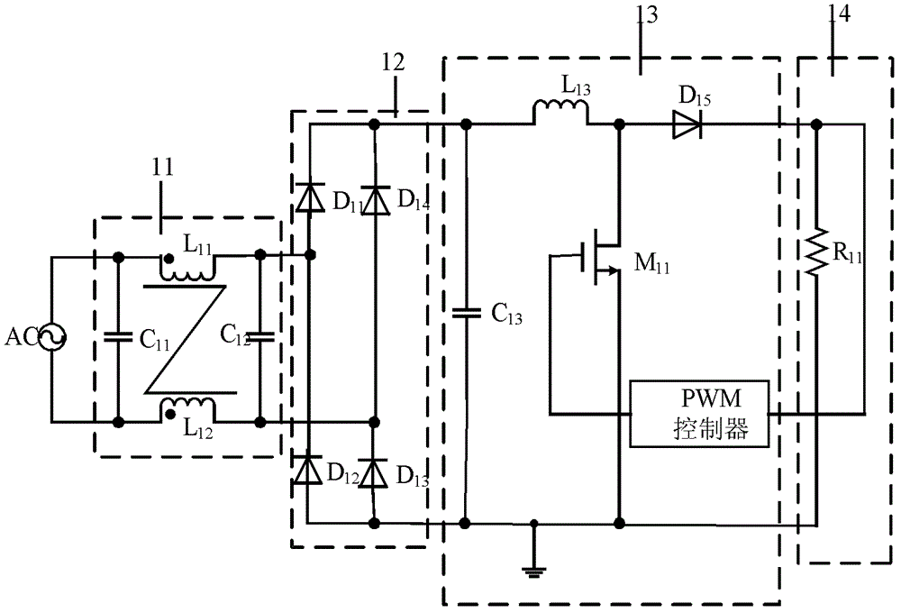
technical field [0001] The invention relates to the field of power supplies, and more specifically, relates to a power factor correction circuit applied in power supplies. Background technique [0002] The AC / DC power supply in the prior art generally includes: EMI (Electromagnetic Interference, electromagnetic interference) filter network, rectifier circuit, power factor correction circuit and power stage circuit, figure 1 It is a working principle block diagram of the AC / DC power supply in the prior art. The alternating current AC is filtered by the EMI filter network 11, and after the electromagnetic interference is eliminated, the voltage output by the EMI filter network 11 is rectified by the full-bridge rectifier circuit 12, and then the voltage output from the full-bridge rectifier circuit 12 is further rectified by the power factor correction circuit 13 power factor correction, and finally input the voltage after power factor correction to the load 14 to drive the l...

Claims


Application Information

Patent Timeline
Patent Type & Authority Patents(China)
IPC IPC(8): H02M1/42H02M1/44
CPCH02M1/4225Y02B70/126Y02B70/10Y02P80/10
Inventor 徐孝如
Owner SILERGY SEMICON TECH (HANGZHOU) CO LTD
Learn More