Inclination adjustment mechanism, imaging device and information terminal provided with inclination adjustment mechanism

A technology of tilt adjustment and camera components, which is applied in the field of camera devices and portable information terminals, can solve problems such as deviation from the set state, and achieve the effects of small changes, high-precision tilt adjustments, and continuous changes in the changes

Inactive Publication Date: 2012-07-25
RICOH KK
View PDF3 Cites 6 Cited by
  • Summary
  • Abstract
  • Description
  • Claims
  • Application Information

AI Technical Summary

Problems solved by technology

[0004] However, in the above-mentioned conventional mounting angle adjustment mechanism, the three leaf springs that exert a force tending to move away from the image pickup element holding frame to the image pickup element holding member are formed by cutting the image pickup element holding member to form a bulge. At the same time as the force tending to leave the imaging element holding frame is applied to the imaging element holding part, a force perpendicular to the direction of the imaging optical axis is also applied. For this reason, the part of the imaging element perpendicular to the direction of the imaging optical axis may Deviate from the set state
In this regard, even if the guide protrusion is used to penetrate the guide through hole in the direction of the photographing optical axis to prevent the occurrence of the above situation, it is difficult to use the guide protrusion to contact the inner peripheral surface of the guide perforation with pressure in the direction perpendicular to the photographing optical axis. Each adjustment screw is used to move the imaging element holding part to the direction of the photographic optical axis

Method used


Image

  • Inclination adjustment mechanism, imaging device and information terminal provided with inclination adjustment mechanism
  • Inclination adjustment mechanism, imaging device and information terminal provided with inclination adjustment mechanism
  • Inclination adjustment mechanism, imaging device and information terminal provided with inclination adjustment mechanism

Examples


Embodiment

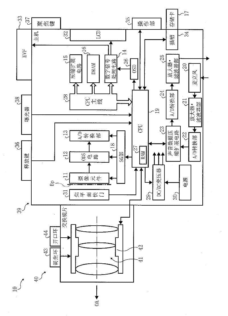
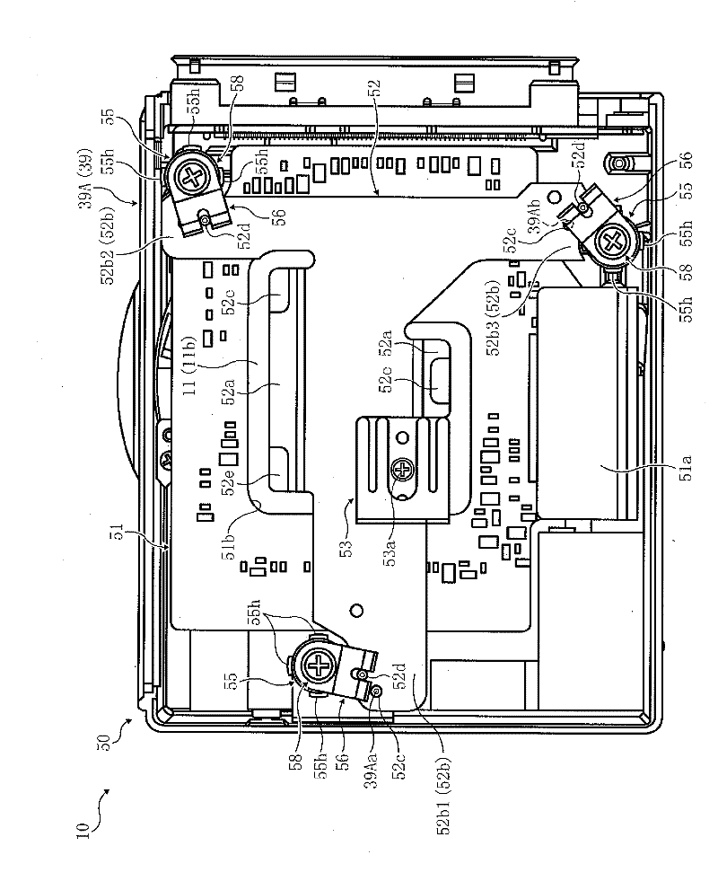
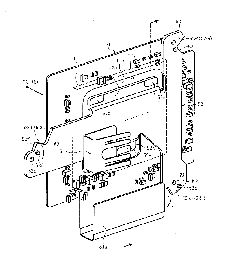
[0049] Use below Figure 1 to Figure 9 The structure of the tilt adjustment mechanism 50 which is an example of the tilt adjustment mechanism of the present invention will be described. first use figure 1 The digital camera 10 equipped with this tilt adjustment mechanism 50 will be described. figure 1 It is a schematic diagram roughly showing the structure of the digital camera 10 . like figure 1 As shown, the digital camera 10 is configured to be used on the camera main body 39 (in the following figure 2 The interchangeable lens part 40 attached to and detached from the casing part 39A), that is, the imaging optical system forms the image of the object to be photographed, and the image of the object is read by the imaging element 11, and the image is appropriately processed. . In addition to the imaging element 11, the digital camera 10 also includes a CDS circuit 12, an A / D conversion circuit 13, a digital signal processing circuit 14, a companding circuit 15, a DRAM 1...


PUM


Abstract

The invention relates to an inclination adjustment mechanism, an imaging device and an information terminal provided with the inclination adjustment mechanism, wherein the inclination adjustment of imaging elements can be realized simply with high accuracy. The inclination adjustment mechanism (50) holds an imaging element (11) and can change the inclination state of the imaging element (11) relative to a basket body (39a), so that the imaging surface (11a) of the imaging element (11) is kept consistent with the reference surface of an imaging optical system. The inclination adjustment mechanism (50) comprises the holder plate (52) of an imaging element (11) and at least three support members (55). Support points for the holder plate (52) are formed on the cam surfaces (55c) of the support members (55). The supported holder plate (52) can move along the adjustment direction of the reference surface. The cam surfaces (55c) can be inclined with respect to the reference surface. Each support member (55) is configured to surround the imaging element (11) in the direction of the reference surface.

Description

technical field [0001] The present invention relates to a tilt adjustment mechanism for tilt adjustment of an imaging element, an imaging device and a portable information terminal equipped with the tilt adjustment mechanism. Background technique [0002] In recent years, there has been a demand not only for miniaturization of digital cameras, but also for further improvement of image quality. To improve the quality of photographic images, it is necessary to arrange the imaging element at a proper position to obtain the subject image formed by the photographic optical system. Therefore, it is necessary to set a reference plane relative to the photographing optical system in the frame. In order to keep the reference plane consistent with the imaging plane of the imaging element, it is necessary to perform high-precision tilt adjustment on the imaging element in the photographing optical system. That is to say, not only the position of the imaging element in the direction of ...

Claims


Application Information

Patent Timeline
Patent Type & Authority Applications(China)
IPC IPC(8): H04N5/232H04N5/225G03B5/00
Inventor 吉田克信篠原纯一
Owner RICOH KK
Why Eureka
Try Eureka