Pre-pressurized hydraulic drive with variable speed pump

A driving device, variable speed technology, used in fluid pressure actuating devices, presses, servo motors, etc., can solve the problems of reducing the economy of hydraulic driving devices, not being widely accepted, etc., to achieve energy saving, short time period Effect

Active Publication Date: 2016-04-27
ROBERT BOSCH GMBH
View PDF7 Cites 0 Cited by
  • Summary
  • Abstract
  • Description
  • Claims
  • Application Information

AI Technical Summary

Problems solved by technology

The consumption of its construction and the number of required hydraulic components and their coordination with one another reduce the economical efficiency of this known hydraulic drive so much that it is not widely accepted in the professional field

Method used


Image

  • Pre-pressurized hydraulic drive with variable speed pump
  • Pre-pressurized hydraulic drive with variable speed pump
  • Pre-pressurized hydraulic drive with variable speed pump

Examples


Embodiment Construction

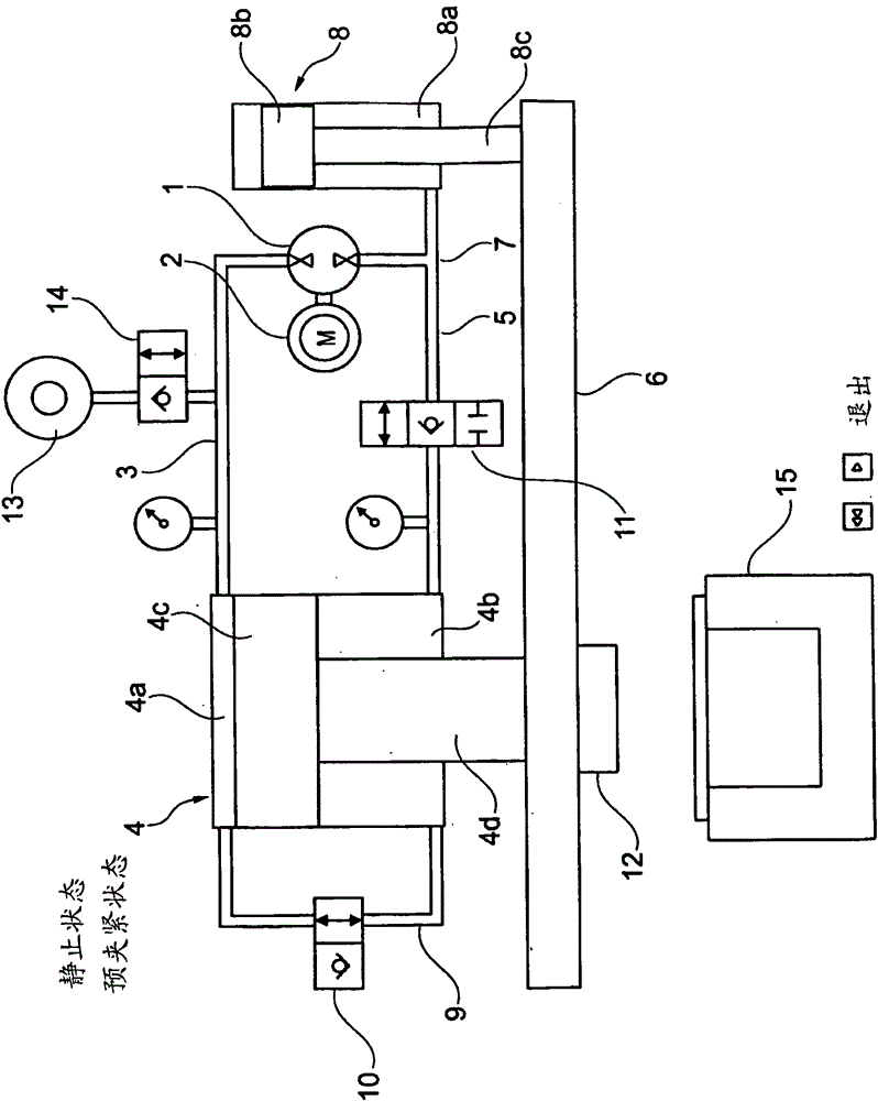
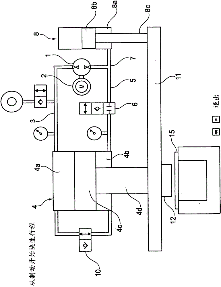
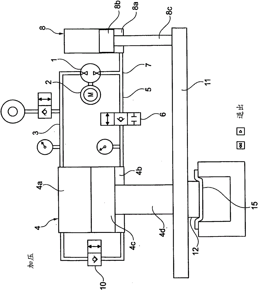
[0017] As can be seen from all the figures, the hydraulic drive according to the invention has a pressure medium source in the form of a variable-speed driven hydraulic machine 1 as a pump, which is mechanically connected to an electric motor 2 for this purpose. The hydraulic machine 1 is connected at its two pressure connections to a pressure piping system forming a closed-loop hydraulic circuit.

[0018] Specifically, a first connecting line 3 is connected to a first pressure connection of the hydraulic machine 1 , said first connecting line leading directly to the piston-side pressure chamber 4 a of the master cylinder 4 . A second line 5 is connected to a second pressure connection of the hydraulic machine 1 , said second line being connected via a valve 6 to a pressure chamber 4 b on the piston rod side of the master cylinder 4 (hereinafter referred to as annular chamber). The valve 6 is currently designed as a directional control valve, in particular as a 3 / 2-way switchi...


PUM


Abstract

The present invention relates to a hydraulic drive with a hydraulic machine (1) activated with variable speed by an electric drive motor (2), a main cylinder (4) for carrying out a sequence of movements while building up force and a secondary cylinder (8) for carrying out a rapid sequence of movements. According to the invention, the hydraulic machine (1), mechanically activated by the drive motor (2), uses one of its pressure connections to prestress at least one piston side of the main cylinder (4) with a predetermined permanent pressure, this hydraulic machine (1) bringing about a reciprocating movement of the main cylinder (4) and of the secondary cylinder (8) on the basis of one of the two sequences of movements by selectively circulating pressure medium in a closed circuit in which the hydraulic machine (1) is included.

Description

technical field [0001] The invention generally relates to hydraulic drives, preferably for presses, plastics machines, bending machines and the like. [0002] Such a drive device is designed to realize at least the following two motion processes: a fast switching motion (hereinafter referred to as "quick stroke") and a force-applying working motion (hereinafter referred to as "pressurization stroke"). Background technique [0003] A hydraulic drive of this type for a press is known from the prior art, for example according to document EP0785861B1. This drive consists of a driven hydrostatic machine which generates a predetermined constant pressure in the primary pressure piping system and a hydraulic transformer consisting of a hydraulic motor and a hydraulic pump mechanically connected to the hydraulic motor. The preferably adjustable hydraulic motor is connected to the primary pressure piping system and is thus driven by the hydrostatic machine. This likewise adjustable ...

Claims


Application Information

Patent Timeline
Patent Type & Authority Patents(China)
IPC IPC(8): B30B15/16F15B11/024
CPCF15B11/024B30B15/161F15B2211/20515F15B2211/20561F15B2211/3058F15B2211/7053F15B2211/7107F15B2211/7114F15B2211/775F15B2211/782F15B2211/785
Inventor S·施密特
Owner ROBERT BOSCH GMBH
Why Eureka
Try Eureka