Application method for covering sewage pool with telescopic steel membrane structure

An application method and technology of sewage tank, applied in the direction of sedimentation tank, etc., can solve the problems of increased sewage treatment cost, reduced equipment service life, poor flexibility, etc., to save land space and human resources, increase service life, and operate without effect of influence

Inactive Publication Date: 2012-08-01
张永进
View PDF2 Cites 1 Cited by
  • Summary
  • Abstract
  • Description
  • Claims
  • Application Information

AI Technical Summary

Problems solved by technology

[0002] Due to the process characteristics of sewage treatment, the current sedimentation tanks have odor. Therefore, in order to control the odor, the existing urban sewage treatment plants must seal the tank body and collect the gas. Since there are sewage treatment equipment in the sedimentation tank, Therefore, when adding a cover, only a reinforced concrete structure sealing room can be built above the pool body; the disadvantages of this method are: firstly, the location of the building is fixed, the flexibility is poor, the building volume is relatively large, and it is necessary to add a cover at one time The investment is large. In order to achieve the treatment effect on the odor, the air volume must be greatly increased, which increases the one-time investment and operating cost of the deodorization equipment. Secondly, because the sewage treatment room is sealed, the indoor odor concentration is high. It is easy to corrode the sewage treatment equipment, resulting in aging or damage of the machine, reducing the service life of the equipment, and the equipment needs to be replaced or repaired, which also increases the cost of sewage treatment

Method used


Image

  • Application method for covering sewage pool with telescopic steel membrane structure
  • Application method for covering sewage pool with telescopic steel membrane structure
  • Application method for covering sewage pool with telescopic steel membrane structure

Examples


Embodiment Construction

[0017] The present invention will be further described below in conjunction with the accompanying drawings and embodiments.

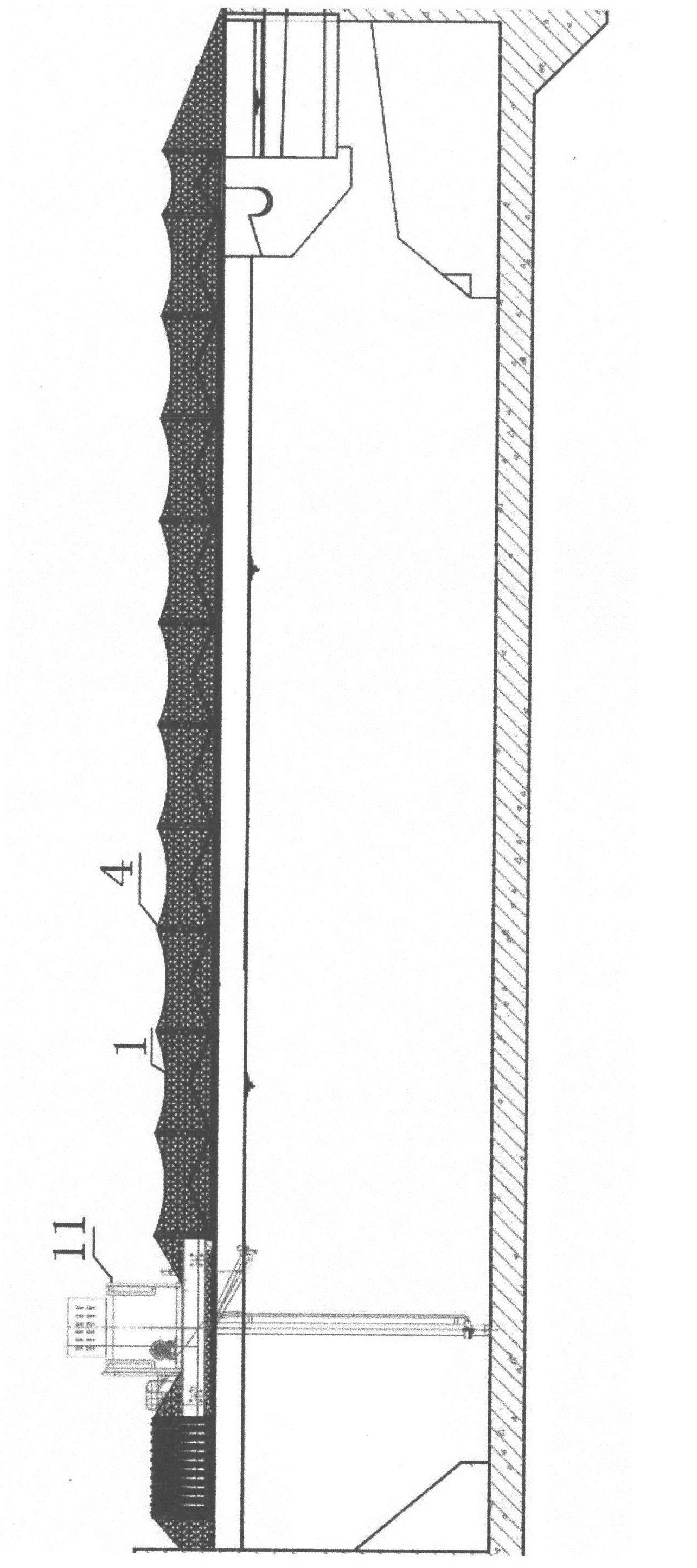
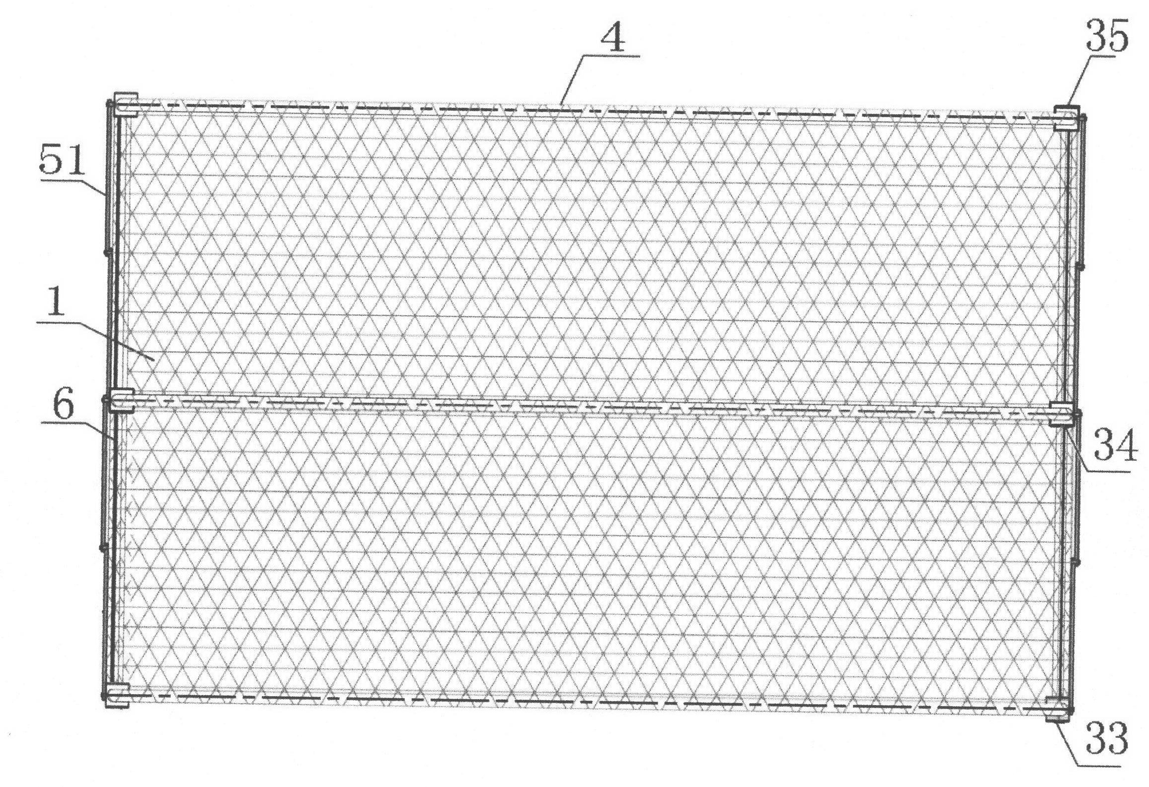
[0018] see Figure 1 to Figure 4 , an application method for capping a telescopic steel film structure in a sewage pool, wherein: the antifouling film 1 is covered on the telescopic support structure by means of telescopic movement, and then the telescopic support structure is connected to the guide rail mechanism; wherein :

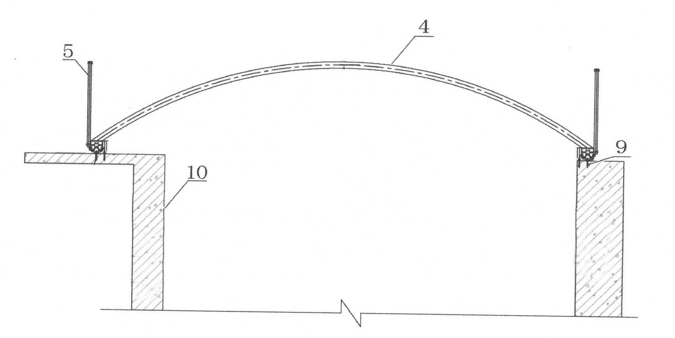
[0019] The guide rail mechanism includes a guide rail and a steel wheel assembly; the guide rail includes a wire guide rail 6 and a T-shaped guide rail 2; the wire guide rail 6 is connected to the steel wheel assembly; the middle part of the upper end of the T-shaped guide rail 2 is provided with a triangular support portion 21. The steel wheel assembly includes a steel wheel shell 3, a roller 31 and a steel wheel center shaft 32;

[0020] The telescopic support structure includes an arc-shaped steel pipe skeleton 4, a support f...


PUM


Abstract

An application method for covering a sewage pool with a telescopic steel membrane structure, which includes the steps: covering an antifouling membrane onto a telescopic support structure in a telescopically moving manner, and then connecting the telescopic support structure with a guide rail mechanism. The guide rail mechanism comprises guide rails and a steel wheel component, the guide rails include a linear guide rail and a T-shaped guide rail, the linear guide rail is connected onto the steel wheel component, a triangular support portion is arranged in the middle of the upper end of the T-shaped guide rail, the steel wheel component comprises steel wheel casings, rolling wheels and steel wheel central shafts, the telescopic support structure comprises an arc steel pipe framework, supporting frames and a plurality of lifting fixing parts, each supporting frame is formed by sequentially hinging four supporting rods, the arc steel pipe framework penetrates through two ends and the middle of the antifouling membrane, the supporting rods of the supporting frames are connected with the lifting fixing parts, and the other end of each lifting fixing part penetrates through a small hole of the antifouling membrane to be fastened with the linear guide rail.

Description

technical field [0001] The invention relates to an application method for covering a sewage pool with a telescopic steel membrane structure. The method utilizes a telescopic device to make the covering of the sewage pool flexible and facilitates the cleaning of slag in the pool by a grab machine of sewage treatment equipment. Background technique [0002] Due to the process characteristics of sewage treatment, the current sedimentation tanks have odor. Therefore, in order to control the odor, the existing urban sewage treatment plants must seal the tank body and collect the gas. Since there are sewage treatment equipment in the sedimentation tank, Therefore, when adding a cover, only a reinforced concrete structure sealing room can be built above the pool body; the disadvantages of this method are: firstly, the location of the building is fixed, the flexibility is poor, the building volume is relatively large, and it is necessary to add a cover at one time The investment is ...

Claims


Application Information

Patent Timeline
Patent Type & Authority Applications(China)
IPC IPC(8): B01D21/02
Inventor 张永进
Owner 张永进
Why Eureka
Try Eureka