
Single cylinder type automatic feed mechanism

An automatic feeding and single-cylinder technology, applied in the field of mechanical feeding mechanism, can solve the problems of synchronous work difference of power source, tilting of materials lifted up, affecting the service life of equipment, etc., and achieve low manufacturing cost and long service life of equipment , The humanized effect of equipment structure design

Active Publication Date: 2014-04-30
KUN SHAN BAO YU PLASTIC CASING
View PDF6 Cites 0 Cited by
  • Summary
  • Abstract
  • Description
  • Claims
  • Application Information

AI Technical Summary

Problems solved by technology

At present, automatic feeding mechanisms are also installed on some processing machines with a high level of automation, such as automatic feeding plastic machines. The existing feeding mechanisms mainly use two side cylinders to work synchronously to lift the material reel up and down. , install it on the material seat of the processing equipment, but the following problems are likely to occur with this mechanical structure: use two cylinders as the power source to pull up the material at the same time and lift it up. Due to the power source itself, the two power sources There may be discrepancies in synchronous work, which may lead to tilting or improper feeding of the materials lifted up; the installation position of the power source is on the side, the weight to be carried is relatively large, and the arm of force is short, which affects the power source. The requirements are very high, which affects the service life of the equipment

Method used


Image

  • Single cylinder type automatic feed mechanism

Examples


Embodiment Construction

[0021] In order to clarify the technical scheme and technical purpose of the present invention, the present invention will be further introduced below in conjunction with the accompanying drawings and specific implementation methods.

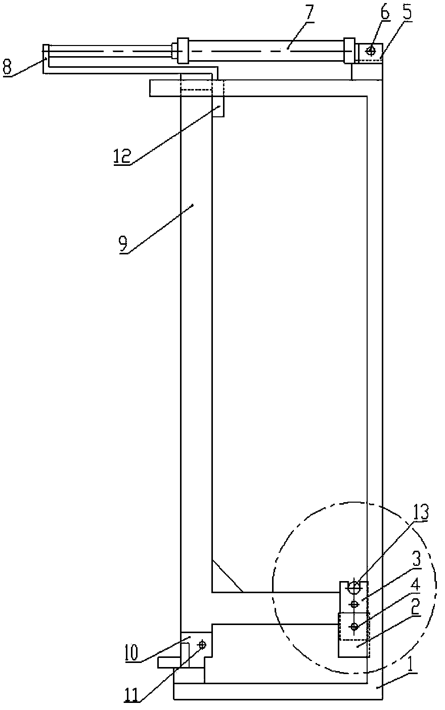
[0022] As shown in the figure, a single-cylinder automatic feeding mechanism is used for feeding plastic blister machines, including the following components:

[0023] 1), fixed frame 1;

[0024] 2), material rack 9;

[0025] The side of the material rack 9 is "L" shaped, including a vertical riser and a horizontal bottom plate arranged at the bottom of the riser. One end of the bottom plate is fixedly connected with the vertical plate, and the free end of the other end is provided with a material seat 3 and a height adjustment base 2 . Viewed from the front, the material rack 9 is provided with a set of vertical plates and bottom plates on both sides. The two vertical plates are connected by push rods. The material seats 3 are arranged symmet...


PUM


Abstract

The invention discloses a single cylinder type automatic feed mechanism. The mechanism comprises a fixed frame, a material frame and a driving device, and is characterized in that: a locking device for positioning the material frame is arranged on the material frame; the fixed frame is provided with a material frame base, the bottom of the material frame is hinged on the material frame base through a shaft pin, and a material base which is used for placing a material is arranged on a bottom plate of the material frame; and the upper part of the fixed frame is provided with the driving device which pushes the material frame to do reciprocating swing by taking the shaft pin as a rotating shaft. When the material is charged, the material frame is inclined, and the material base is descended to a lowest position, so that workers can easily place the material on the material base, and the material is not required to be lifted; and then the material frame is upwards rotated to the material base under the control of the driving device, and is fixed by using the locking device. The waste of manpower which is caused by the manual lifting of the material is avoided, the work efficiency of workers is improved, and the mechanism has a simple structure, is low in cost, and can be conveniently popularized and applied in the industrial machining of production lines.

Description

technical field [0001] The invention relates to a mechanical feeding mechanism, which is especially suitable for feeding sheets and rolls. Background technique [0002] In industrial production and processing, installing an automatic feeding mechanism on the production line can effectively reduce the labor intensity of workers, reduce processing steps, and improve production efficiency. It is an important way to improve the level of automated production. At present, automatic feeding mechanisms are also installed on some processing machines with a high level of automation, such as automatic feeding plastic machines. The existing feeding mechanisms mainly use two side cylinders to work synchronously to lift the material reel up and down. , install it on the material seat of the processing equipment, but the following problems are likely to occur with this mechanical structure: use two cylinders as the power source to pull up the material at the same time and lift it up. Due t...

Claims


Application Information

Patent Timeline
Patent Type & Authority Patents(China)
IPC IPC(8): B29C31/04B29C51/26B29C51/10
Inventor 黄立强
Owner KUN SHAN BAO YU PLASTIC CASING
Learn More