Mould for manufacturing glass container

A glass container and mold technology, which is applied in the field of molds for making glass containers, can solve problems such as inconsistencies, and achieve the effects of smooth molding, saving resources, and reducing the matching area.

Active Publication Date: 2013-11-06
CHANGSHU JIANHUA MOLD TECH
View PDF3 Cites 0 Cited by
  • Summary
  • Abstract
  • Description
  • Claims
  • Application Information

AI Technical Summary

Problems solved by technology

Also, the applicant found that in the prior art, the sides of a pair of bottle half-molds facing each other, that is, the surfaces of the side of the seam are treated equally. The so-called equal treatment refers to the position of the bottle neck, The bottom part of the bottle, the cavity part and the peripheral parts are all designed to be of equal height, and inconsistencies are avoided

Method used


Image

  • Mould for manufacturing glass container

Examples


Embodiment 1

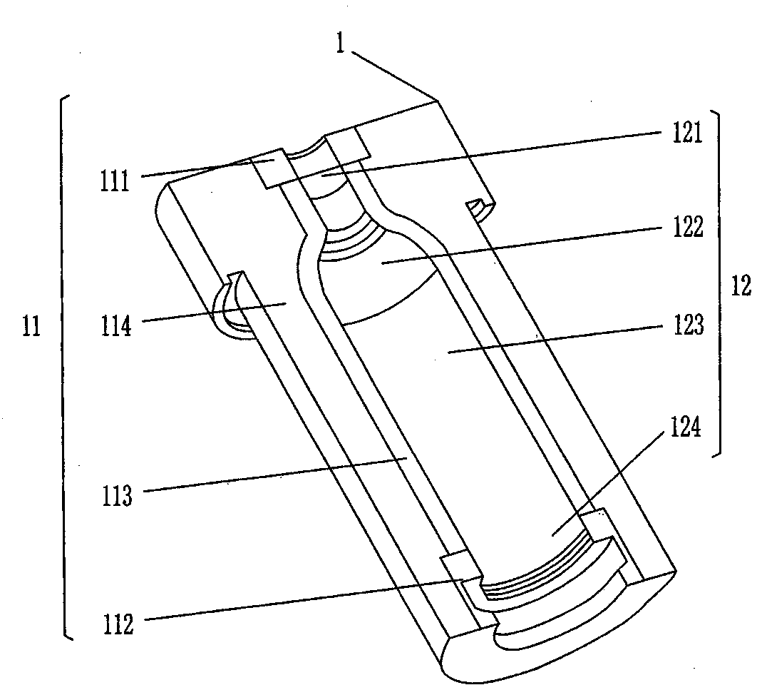
[0011] see figure 1 , since the shape of a pair of bottle half molds 1 is the same, only one bottle half mold 1 is shown in the figure, and the inner side of the bottle half mold 1 faces the side of the other bottle half mold 1 in the use state A pair of seam surfaces 11 are formed, and the pair of seam surfaces 11 are located on both sides of the bottle mold cavity 12 in the height direction, wherein: the bottle mold cavity 12 is composed of a bottle neck cavity 121, a neck shoulder cavity 122, a bottle body cavity 123 and a bottle bottom cavity. 124 are formed together (belonging to common knowledge), and the seam surface 11 includes the bottle mouth fitting area 111 corresponding to the mouth of the bottle neck cavity 121 and the middle fitting area 113 corresponding to the mouth of the bottle body cavity 123. , Corresponding to the bottle bottom matching area 112 at the mouth of the bottle bottom cavity 124 and the peripheral matching area 114 located in the middle matc...

Embodiment 2

[0014] The figure is omitted, only the height of the surface of the middle matching area 113 is changed to be 0.5 mm lower than the surface of the bottle mouth and bottle bottom matching areas 111 and 112, and the height of the surface of the peripheral matching area 114 is changed to be higher than that of the middle matching area 113. The surface is 0.1 mm lower, and the width of the middle matching area 113 is changed to 15 mm, and the rest are the same as the description of Embodiment 1.

Embodiment 3

[0016] The figure is omitted, only the height of the surface of the middle matching area 113 is changed to be 0.9 mm lower than the surface of the bottle mouth and bottle bottom matching areas 111 and 112, and the height of the surface of the peripheral matching area 114 is changed to be higher than that of the middle matching area 113. The surface is 1 mm lower, and the width of the middle matching area 113 is changed to 7 mm, and the rest are the same as the description of Embodiment 1.

[0017] The mold obtained by the above-mentioned Examples 1-3 was handed over to the glass container manufacturer for trial in the state that the applicant took strict confidentiality measures. 2 times longer service life), thus confirming the technical effect described by the applicant .


PUM

PropertyMeasurementUnit
widthaaaaaaaaaa

Abstract

The invention provides a mould for manufacturing a glass container, belonging to the technical field of a glass mould. The mould comprises a pair of bottle half modules, wherein each bottle half module is provided with a joint close surface and a bottle mould chamber composed of a bottleneck chamber, a neck shoulder chamber, a bottle body chamber and a bottle bottom chamber; the joint close surface comprises a bottle opening matching region located at the chamber opening part of the bottleneck chamber, a middle matching region corresponding to the chamber opening part of the bottle body chamber, a bottle bottom matching region corresponding to the chamber opening part of the bottle bottom chamber, and a peripheral matching region located at the outer side of the middle matching region. The mould is characterized in that: the planes of the bottle opening matching region and the bottle bottom matching region are located at the same height, the plane of the middle matching region is lower than the plane of the bottle opening matching region, and the plane of the peripheral matching region is lower than the middle matching region. The mould provided by the invention has the advantages that: a matching area of the matching surface is reduced, the deformation amount of the mould in a work process is compensated, the production efficiency is improved, the service life is prolonged, and the resource is saved.

Description

technical field [0001] The invention belongs to the technical field of glass moulds, in particular to a mold for making glass containers. Background technique [0002] Glass containers such as glasses, cosmetic bottles, all kinds of pickle bottles, vases, wine bottles and beverage bottles, etc., all need to rely on a pair of bottle half molds that are matched face to face. As known in the industry, in the process of using glass molds to produce glass containers, molten glass frit at 1100°C is introduced into the cavity of the glass mold, and the mold temperature drops rapidly to 650°C within 3-6 seconds. In this process, because the glass mold material is subjected to factors such as growth, oxidation and thermal fatigue, glass container manufacturers often find that although the life of the glass mold has not yet ended, the mold has already deformed And seriously affect the use, even if it is to barely maintain the mold that continues to be used, it needs to be frequently ...

Claims


Application Information

Patent Timeline
Patent Type & Authority Patents(China)
IPC IPC(8): C03B9/32
CPCY02P40/57
Inventor 马建华周冰朱伟国方朝辉石明强
Owner CHANGSHU JIANHUA MOLD TECH
Why Eureka
Try Eureka