Multi-layer variable geometric volute device

A volute and geometry technology, applied in the field of multi-layer variable geometry volute devices, can solve the problems of high negative pressure difference between the intake and exhaust of the engine, affecting the performance of the engine, and high pumping loss, so as to increase the boosting ratio and simple structure , good inheritance effect

Inactive Publication Date: 2012-08-01
KANGYUE TECH
View PDF8 Cites 9 Cited by
  • Summary
  • Abstract
  • Description
  • Claims
  • Application Information

AI Technical Summary

Problems solved by technology

However, the problem in practical application is that the negative pressure difference between the intake and exhaust of the engine is very high, and the pumping loss is too high, resulting in high fuel consumption under low-speed engine conditions.
However, under the medium and high-speed working conditions of the engine, there is an airflow mixing phenomenon in the inlet flow channel of the outer flow channel of the volute, and the backflow phenomenon from the air storage to the outer flow channel of the volute at the point where the angle of the air intake area of ​​the inner flow channel of the volute is the largest is This affects the performance of the engine at medium and high operating conditions

Method used


Image

  • Multi-layer variable geometric volute device
  • Multi-layer variable geometric volute device
  • Multi-layer variable geometric volute device

Examples


Embodiment 1

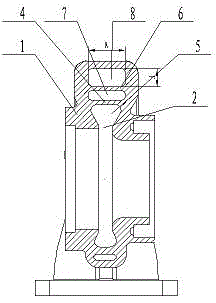
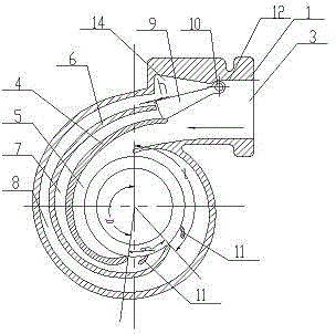
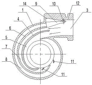
[0058] Example 1, such as figure 1 , figure 2 As shown, a multi-layer variable geometry volute device includes a turbine volute 1, which is provided with a volute inlet flow passage and a bladeless nozzle 2, and the turbine volute 1 is provided with and The volute air inlet 3 connected with the volute air inlet flow channel;

[0059] A first aerodynamic partition 4 is provided in the volute air inlet flow path, and the first aerodynamic partition 4 divides the volute air inlet flow path into a volute air inlet inner flow path 5 and a volute air inlet outer flow path;

[0060] A second aerodynamic partition 6 is provided in the volute air inlet outer flow path, and the second aerodynamic partition 6 divides the volute air inlet outer flow path into a first branch flow path 7 and a second branch flow path 8;

[0061] The volute air intake inner flow passage 5 is a normally open intake flow passage;

[0062] In the volute air inlet flow path, an air inlet regulating valve 9 for controll...

Embodiment 2

[0079] Example 2, such as Figure 5 As shown, in Embodiment 1, the cross-sectional shape of the air intake adjusting valve 9 may also be a rectangular structure, and the air intake adjusting valve shaft 10 is arranged on the second pneumatic partition 6 at the end close to the end of the air inlet 3. Department location.

[0080] The ratio of the distance between the center position of the intake control valve shaft 10 and the end of the intake control valve 9 near the first pneumatic partition 4 to the center of the intake control valve shaft 10 to the distance between the intake control valve 9 and the inner wall 12 of the volute The range is 1 / 4~1 / 2.

[0081] In order to ensure that the air intake regulating valve 9 achieves a good sealing fit with the inner wall 12 of the volute and the first pneumatic partition 4, both ends of the air intake regulating valve 9 are inclined surface structures. The partition plate 4 is respectively provided with mating surfaces that are matched...

Embodiment 3

[0085] Example 3, such as Figure 8 , Picture 9 As shown, in the above-mentioned embodiment 2, the intake regulating valve shaft 10 may also be arranged at an end of the intake regulating valve 9 close to the first pneumatic partition 4.

[0086] The end of the intake control valve 9 away from the intake control valve shaft 10 has a slope structure, and the inner wall 12 of the volute and the second pneumatic partition 6 are respectively provided with mating surfaces that cooperate with the intake control valve 9.

[0087] According to the position of the intake control valve shaft, the ratio of the intake area angle β of the first branch flow passage 7 and the intake area angle γ of the second branch flow passage 8 ranges from 6:1 to 2:1. Make any adjustments according to the situation.

[0088] The ratio of the cross-sectional area of ​​the second branch flow channel 8 to the cross-sectional area of ​​the first branch flow channel 7 ranges from 1 / 4 to 1 / 2.

[0089] Two to three gui...


PUM


Abstract

The invention discloses a multi-layer variable geometric volute device, which comprises a turbine volute. A volute air inlet passage and a non-blade nozzle are arranged in the turbine volute, and a volute air inlet communicated with the volute air inlet passage is arranged on the turbine volute. A first pneumatic partition plate is arranged in the volute air inlet passage and partitions the volute air inlet passage into a volute air inlet inner passage and a volute air inlet outer passage. A second pneumatic partition plate is arranged in the volute air inlet outer passage and partitions the volute air inlet outer passage into a first branch passage and a second branch passage. The volute air inlet inner passage is a normally-opened air inlet passage. An air inlet adjustment valve for controlling the opening or the closing of the first branch passage and the second branch passage is arranged in the volute air inlet passage close to the volute air inlet. The air inlet adjustment valve can guide the air flow flowing into the volute air inlet inner passage simultaneously when the air inlet adjusting valve is opened or closed. The air inlet adjustment device is simple in structure, the control mode can be easily implemented, and the reliability is high.

Description

Technical field [0001] The invention relates to a multi-layer variable-geometry volute device, in particular to a multi-layer variable-geometry volute device that meets the performance requirements of the engine under various operating conditions through different flow channels working individually and together, and belongs to the internal combustion engine field. Background technique [0002] In recent years, with the increasingly stringent emission regulations, turbocharging technology has received more and more attention. Under the premise of basically not consuming the effective power of the engine, the turbocharging technology uses the exhaust gas energy from the engine to drive the turbine to do work, and supercharge the engine intake through the compressor; in addition, the turbine has the effect of reducing engine emission noise. Therefore, turbocharging technology has become one of the technical means to deal with the energy crisis and meet emission standards. [0003] T...

Claims


Application Information

Patent Timeline
Patent Type & Authority Applications(China)
IPC IPC(8): F02B37/22F01D25/24F01D17/10
CPCF02B37/18Y02T10/144F01D9/026F01D17/148F01D17/18F02B37/025F02B37/22Y02T10/12
Inventor 王航袁道军王艳霞宋丽华李永泰朱智富刘迎鑫
Owner KANGYUE TECH
Why Eureka
Try Eureka