Hybrid flow variable spiral case

A hybrid and volute technology, applied to engine components, machines/engines, internal combustion piston engines, etc., can solve the problems of high negative pressure difference between the intake and exhaust of the engine, affecting engine performance, high pumping loss, etc., to achieve increased boost ratio, easy control method, and good inheritance effect

Active Publication Date: 2013-09-11
康跃科技(山东)有限公司
View PDF7 Cites 0 Cited by
  • Summary
  • Abstract
  • Description
  • Claims
  • Application Information

AI Technical Summary

Problems solved by technology

However, the problem in practical application is that the negative pressure difference between the intake and exhaust of the engine is very high, and the pumping loss is too high, resulting in high fuel consumption under low-speed engine conditions.
However, under the medium and high-speed working conditions of the engine, the mixed flow of the air flow in the inlet flow channel of the outer flow channel of the volute is prone to occur, and the air flow backflows to the outer flow channel of the volute at the point where the air intake area of ​​the inner flow channel of the volute has the largest angle, which affects the Improved engine performance under medium and high operating conditions

Method used


Image

  • Hybrid flow variable spiral case
  • Hybrid flow variable spiral case
  • Hybrid flow variable spiral case

Examples


Embodiment 1

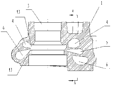
[0039] Example 1, such as figure 1 , figure 2 , image 3 As shown, a hybrid variable flow volute includes a turbine volute 1, a volute inlet flow passage and a volute nozzle ring 13 are arranged in the turbine volute 1, and a volute is provided at one end of the volute inlet flow passage Shell air inlet 2, the other end is provided with volute air outlet 3.

[0040] The volute air intake channel is separated into three channels arranged up and down through the partition: the first air intake channel 4, the second air intake channel 5 and the third air intake channel 6, the first air intake channel 4, the second air intake channel The air passage 5 and the third air intake passage 6 communicate with the air inlet 2 of the volute respectively.

[0041] The first air intake channel 4 is a normally open air intake channel; the first air intake channel 4 realizes the full-circle air intake of 0-360 degrees in the circumferential direction;

[0042] The air intake area angle α ...

Embodiment 2

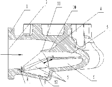
[0053] Example 2, such as Figure 6 , Figure 7 , Figure 8 As shown, this embodiment is another improvement on the basis of Embodiment 1, a hybrid variable flow volute, including a turbine volute 1, and the volute inlet flow passage is arranged inside the turbine volute 1 .

[0054] One end of the volute air intake channel is provided with a volute air inlet 2 and the other end is provided with a volute air outlet 3 .

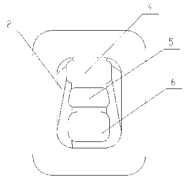
[0055] The volute air intake channel includes three working channels: the first air intake channel 4, the second air intake channel 5 and the third air intake channel 6, the first air intake channel 4, the second air intake channel 5 and the third air intake channel The air passages 6 communicate with the air inlets 2 of the volute respectively.

[0056] The second air intake channel 5 and the first air intake channel 4 are arranged vertically; the third air intake channel 6 and the second air intake channel 5 are arranged side by side.

[0057] A pluralit...

Embodiment 3

[0063] Embodiment 3, above-mentioned embodiment 1 and embodiment 2 are adapted to constant pressure supercharging engine, as Figure 11 As shown, by combining two identical structures (two sets of flow passages) designed in embodiment 1 and embodiment 2 in a certain way (each set of flow passages corresponds to one engine exhaust manifold flow passage) to adapt to For the pulse supercharged engine, there are two volute air inlets designed at this time.

[0064] The design of the volute inlet flow channel is not limited to the above-mentioned three embodiments where the volute inlet flow channel is divided into three flow channels: the first air intake channel, the second air intake channel and the third air intake channel. For special requirements, the second air intake channel is divided into several air intake channel branches, and the third air intake channel is divided into several air intake channel branches. According to the arrangement of the two flow passage structure...


PUM


Abstract

Disclosed is a mixed variable flow volute, comprising a turbine volute (1) within which are provided a volute intake flow path and a volute nozzle ring (13). One end of the volute intake flow path is provided with a volute air-inlet (2), and the other end thereof is provided with a volute air-outlet (3); the volute intake flow path is divided into three flow paths via partitions, i.e. a first intake flow path (4), a second intake flow path (5) and a third intake flow path (6), each of which is in communication with the volute air-inlet (2); the first intake flow path (4) is a normally open intake flow path; and intake control valves (7) are provided in the second intake flow path (5) and the third intake flow path (6) close to the volute air-inlet (2), the intake control valves (7) being able to be opened or closed depending on the operating speed of the engine so as to open or close at least one of the second intake flow path (5) and the third intake flow path (6). The mixed variable flow volute has a simple structure, low cost, high reliability and is easy to control.

Description

technical field [0001] The invention relates to a variable flow volume volute, specifically, through an air intake regulating device, different flow channels can work independently or jointly to meet the performance requirements of various working conditions of the engine, and can improve the performance of the engine at medium speed working conditions. A hybrid variable flow volute belongs to the field of internal combustion engines. Background technique [0002] With the increasingly stringent requirements of emission regulations, people are increasingly demanding a turbocharger that can take into account the performance of the engine under all operating conditions. Because the variable geometry turbocharger (VGT) can effectively control the exhaust pressure of the engine, it can It has become the focus of research and development to achieve a good performance match between the turbocharger and the engine under various working conditions. A variety of variable cross-secti...

Claims


Application Information

Patent Timeline
Patent Type & Authority Patents(China)
IPC IPC(8): F02B37/18F02B37/22
CPCF01D25/24F05D2220/40F02B37/22Y02T10/144F01D17/18Y02T10/12
Inventor 王航李永泰朱智富袁道军王艳霞宋丽华张金明
Owner 康跃科技(山东)有限公司
Why Eureka
Try Eureka