Tidal current energy water turbine runner and its water turbine

A water turbine and tidal current energy technology, which is applied in the direction of machines/engines, mechanical equipment, hydropower, etc., can solve problems such as large-scale development, and achieve the effects of increasing available energy, high energy utilization rate, and high work efficiency

Active Publication Date: 2019-04-16
DONGFANG ELECTRIC MACHINERY
View PDF6 Cites 0 Cited by
  • Summary
  • Abstract
  • Description
  • Claims
  • Application Information

AI Technical Summary

Problems solved by technology

However, due to the short history of development, tidal current power generation has not yet had a large-scale developed technology in the world in terms of basic research and industrial operation, especially in the research of energy conversion devices.

Method used


Image

  • Tidal current energy water turbine runner and its water turbine
  • Tidal current energy water turbine runner and its water turbine
  • Tidal current energy water turbine runner and its water turbine

Examples


Embodiment 1

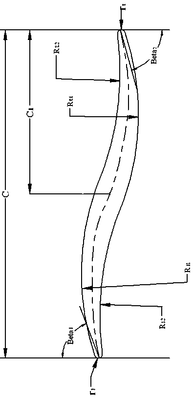
[0039] In this embodiment, the diameter D of the runner is 1483mm. The section of the runner blade is a hyperbolic airfoil composed of the first airfoil and the second airfoil. At the runner diameter D, the chord length C of the blade airfoil is 0.3D, and the leading edge radius of the airfoil is r 1 is 0.004D, the airfoil trailing edge radius r t is 0.004D, the radius R of the blade back profile of the first airfoil where the leading edge of the airfoil is located 11 is 0.2D, and the radius R of the leaf pot shape line 12 is 0.25D, the blade back profile radius R of the second airfoil part where the trailing edge of the airfoil is located t1 is 0.2D, and the radius R of the leaf pot shape line t2 is 0.25D, the placement angle Beta of the first airfoil of the blade 1 is 68°, the placement angle Beta of the second airfoil 2 is 70°. The airfoil chord length C of the second airfoil part 1 is 0.15D.

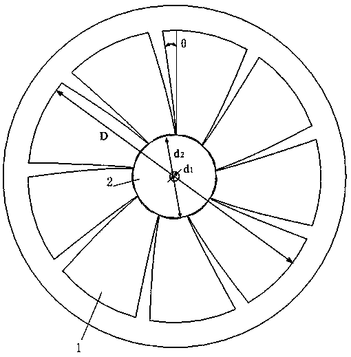
[0040] Nine pieces of blades 1 are arranged on the runner, and the cross...

Embodiment 2

[0045] In this embodiment, the diameter D of the runner is 1483mm. The section of the runner blade is a hyperbolic airfoil composed of the first airfoil and the second airfoil. At the runner diameter D, the chord length C of the blade airfoil is 0.35D, and the leading edge radius of the airfoil is r 1 is 0.005D, the airfoil trailing edge radius r t is 0.005D, the radius R of the blade back profile of the first airfoil where the leading edge of the airfoil is located 11 is 0.3D, and the radius R of the leaf pot shape line 12 is 0.35D, the blade back profile radius R of the second airfoil where the trailing edge of the airfoil is located t1 is 0.3D, and the radius R of the leaf pot shape line t2 is 0.35D, the placement angle Beta of the first airfoil of the blade 1 is 71°, the placement angle Beta of the second airfoil 2 is 74°. The airfoil chord length C of the second airfoil part 1 is 0.175D.

[0046] Nine pieces of blades 1 are arranged on the runner, and the cross-se...

Embodiment 3

[0051] In this embodiment, the diameter D of the runner is 1483 mm. The section of the runner blade is a hyperbolic airfoil composed of the first airfoil and the second airfoil. At the runner diameter D, the chord length C of the blade airfoil is 0.325D, and the leading edge radius of the airfoil is r 1 is 0.0045D, the airfoil trailing edge radius r t is 0.0045D, and the blade back profile radius R of the first airfoil part where the leading edge of the airfoil is located 11 is 0.25D, and the radius R of the leaf pot shape line 12 is 0.30D, the blade back profile radius R of the second airfoil part where the trailing edge of the airfoil is located t1 is 0.25D, and the radius R of the leaf pot shape line t2 is 0.30D, the placement angle Beta of the first airfoil of the blade 1 is 70°, the placement angle Beta of the second airfoil 2 is 72°. The airfoil chord length C of the second airfoil part 1 is 0.16D.

[0052] Nine pieces of blades 1 are arranged on the runner, and ...


PUM


Abstract

The invention belongs to the technical field of fluid flow machine power generation, and discloses a tidal current energy water turbine runner and a water turbine, in particular to a tidal current energy water turbine runner with the blade section being of a hyperbolic wing type, and a water turbine. Blades of the tidal current energy water turbine runner are designed in a non-completely-centrosymmetrical hyperbolic structure, so that the water turbine runner can effectively work in the forward flow incoming process and the backward flow incoming process; and meanwhile, the nonsymmetrical design of the blade wing profile can guarantee that a unit can better adapt to a backward incoming flow and the wing profile can be always kept at a proper incoming flow angle, and the energy utilization efficiency can be effectively improved.

Description

technical field [0001] The invention relates to a tidal energy water turbine, in particular to a tidal energy water turbine with hyperbolic blades, belonging to the technical field of fluid mechanical power generation. Background technique [0002] There are two pillars in my country's energy utilization structure: one is coal-based thermal power generation, and the other is large and medium-sized hydropower generation. The utilization of new energy is not only inefficient but also occupies a small proportion in the energy structure. With the rapid development of social economy, some contradictions in my country's energy utilization have begun to emerge, such as insufficient total energy, simple energy structure, and extremely unbalanced energy distribution in regions. The Copenhagen Conference put forward stricter requirements on China's energy consumption, and must reduce the consumption of fossil energy. In order to cope with global warming, it is of great significance ...

Claims


Application Information

Patent Timeline
Patent Type & Authority Patents(China)
IPC IPC(8): F03B3/12
CPCY02E10/20
Inventor 贺建华刘德民赵永智程宦石清华
Owner DONGFANG ELECTRIC MACHINERY
Why Eureka
Try Eureka