Lining pipe joint of marine oil pipeline
A technology for oil pipelines and lined pipes, which is applied in the direction of pipes/pipe joints/fittings, pipeline protection, hose connection devices, etc., and can solve problems such as poor mechanical strength
- Summary
- Abstract
- Description
- Claims
- Application Information
AI Technical Summary
Problems solved by technology
Method used
Image

Examples
specific Embodiment approach 1
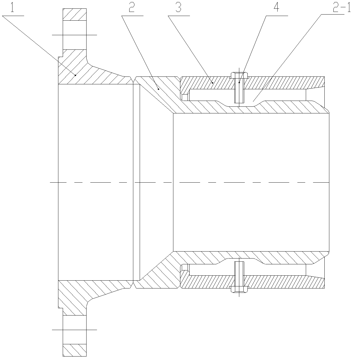
[0010] Embodiment 1: In this embodiment, the lined pipe joint of the ocean oil pipeline includes a flange 1, an inner sleeve 2, an outer sleeve 3 and a plurality of jacking screws 4, and the inner sleeve 2 is arranged inside the outer sleeve 3 and The inner sleeve 2 is coaxial with the outer sleeve 3, the flange 1 is fixed to one end of the inner sleeve 2 and the outer sleeve 3 and is coaxial with the two, and the outer surface of the inner sleeve 2 is provided with an annular concave hole. Groove 2-1, the outer sleeve 3 is evenly opened with a plurality of threaded holes along the circumferential direction, each top wire 4 is screwed in a threaded hole and the front end of the top wire 4 extends into the inner surface of the outer sleeve 3, the top The groove 2-1 on the outer surface of the inner sleeve 2 is pushed against the wire 4 .
[0011] Beneficial effects of the present invention: Since the present invention uses top wires instead of metal rings and throat hoops to fi...
specific Embodiment approach 2
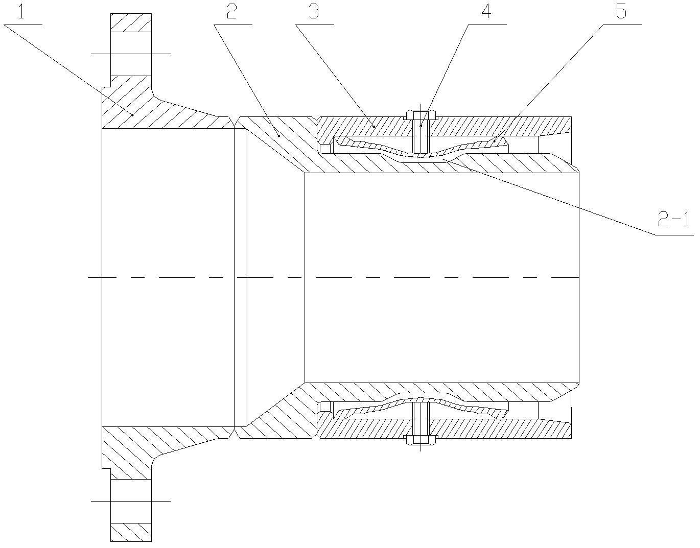
[0012] Specific embodiment two: the difference between this embodiment and specific embodiment one is that a connecting sleeve 5 is added between the inner sleeve 2 and the outer sleeve 3, and the connecting sleeve 5 is fixed on the outer sleeve 3, and the top wire The front end of 4 is pressed against the outer surface of the connecting sleeve 5, and the inner surface of the connecting sleeve 5 deformed under pressure fills the groove 2-1. Other structures and connections are the same as in the first embodiment.
[0013] This structure can effectively avoid the stress concentration on the surface of the liner pipe caused by the long-term top pressure of the top wire. The result of stress concentration will cause local damage to the liner pipe and affect the normal operation of marine oil transportation.
specific Embodiment approach 3
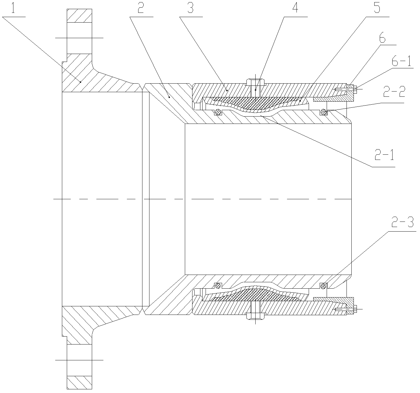
[0014] Specific embodiment three: the difference between this embodiment and specific embodiment two is that: the two ends of the connecting sleeve 5 are fixed on the outer sleeve 3 by welding, and the outer circular surface of the connecting sleeve 5 is connected to the outer sleeve 3. A cavity is formed between the surfaces of the inner holes, and two annular sealing grooves 2-2 are formed on the outer surface of the inner sleeve 2, and the cavity between the connecting sleeve 5 and the outer sleeve 3 is filled with rings. Oxygen resin, injection of epoxy resin and exhaust are realized through two threaded holes corresponding to the top wire 4, and a sealing ring 2-3 made of nitrile rubber is placed in the sealing groove 2-2. Other structures and connections are the same as in the second embodiment.
[0015] In this structure, the epoxy resin also plays the role of crimping, and its mechanical properties are very good. During the cooling process, the solidification shrinkag...
PUM
 Abstract
Description
Claims
Application Information
 - R&D
- Intellectual Property
- Life Sciences
- Materials
- Tech Scout
- Unparalleled Data Quality
- Higher Quality Content
- 60% Fewer Hallucinations
Browse by: Latest US Patents, China's latest patents, Technical Efficacy Thesaurus, Application Domain, Technology Topic, Popular Technical Reports.
© 2025 PatSnap. All rights reserved.Legal|Privacy policy|Modern Slavery Act Transparency Statement|Sitemap|About US| Contact US: help@patsnap.com