Heat pump defrosting system in winter

A technology of heat pump and heat source, applied in the field of heat pump winter defrosting system, which can solve the problems of high-grade electric energy consumption and non-conforming to low-carbon energy saving

Inactive Publication Date: 2012-08-01
DONGHUA UNIV
View PDF7 Cites 7 Cited by
  • Summary
  • Abstract
  • Description
  • Claims
  • Application Information

AI Technical Summary

Problems solved by technology

The advantage of this method is that the room temperature fluctuation is small during the defrosting process, the pressure change is stable when the defrosting is switched, and there will be no four-way valve reversing airflow noise when starting and stopping the defrosting; the disadvantage is that it consumes high-grade electric energy At the cost, it does not conform to the concept of low-carbon energy saving

Method used


Image

  • Heat pump defrosting system in winter
  • Heat pump defrosting system in winter
  • Heat pump defrosting system in winter

Examples


Embodiment 1

[0026] like Figure 4 and Figure 5 As shown, the pcm module and the indoor coil 111 of the indoor unit are made in the form of a sleeve 11 and installed on the heat dissipation fins 12 of the indoor unit; the pcm medium 112 of the pcm module surrounds the sleeve 11 outside. The indoor unit fan stops during defrosting. The heat required for defrosting is all provided by the storage heat and latent heat of phase change of the pcm medium. In the normal heating stage before defrosting, the pcm medium is heated by the indoor return air, and the pcm medium is in a liquid state. After switching to the defrost mode, the evaporation temperature of the indoor unit is lower than the phase transition temperature of the pcm medium, so the solution is feasible. In order to increase the heat exchange between the indoor unit and the medium in the pcm module, copper fins are evenly installed in the casing.

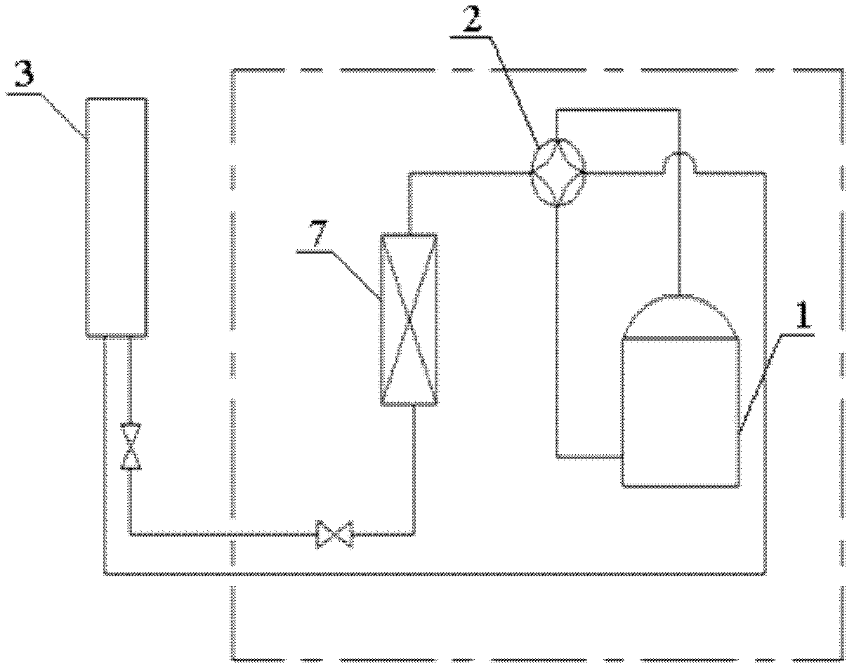
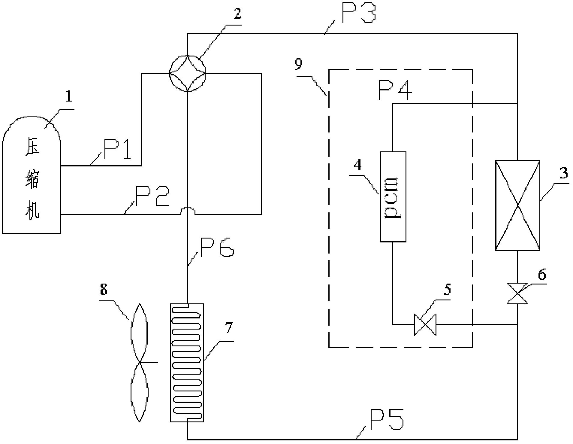
[0027] see image 3 (There is no part 9 at this time), the heat pump starts norm...

Embodiment 2

[0030] like Image 6 As shown, the pcm module and the indoor coil 111 of the indoor unit are arranged independently; the pcm module 4 is installed at the air outlet of the indoor unit; the indoor coil 111 is installed on the heat dissipation fins 12 of the indoor unit superior. like Figure 7 and Figure 8 As shown, the pcm module is a shuttle type or a sheet type; the outer periphery of the pcm module is a metal sheet 114, and the inside is a pcm medium 112, and the pcm medium 112 is provided with a refrigerant pipeline for connecting with the condenser of the indoor unit .

[0031] see image 3 (At this time, there is part 9), the heat pump starts normally and runs in a frost-free state. At this time, the circuit controls the throttle valve 5 to close and 6 to open. The refrigerant exits the compressor through pipelines P1 and P3 and then enters the indoor unit 3. The principle at this stage is the same as that of Scheme 1; Image 6As shown in the figure, the pcm modul...

Embodiment 3

[0034] like Figure 4 and Figure 5 As shown, the pcm module and the indoor coil 111 of the indoor unit are made in the form of a sleeve 11 and installed on the heat dissipation fins 12 of the indoor unit; the pcm medium 112 of the module is surrounded by the sleeve 11 . Another pcm module is arranged independently of the indoor coil 111 of the indoor unit, and is installed at the air outlet of the indoor unit.

[0035] The operation is basically the same as in Example 2, the difference is the defrosting stage image 3 The middle solenoid valves 5 and 6 are both open, and the refrigerant absorbs heat not only from the pcm medium on the casing, but also from the pcm medium at the tuyere of the indoor unit.

[0036] Describe the present invention with an example below, choose McQuay 1HP split type heat pump air conditioner to calculate, and its specification parameter is as follows:

[0037]

Cooling capacity (kw)

Heating capacity (kw)

Cooling power (kw) ...


PUM


Abstract

The invention relates to a heat pump defrosting system in winter. The system comprises a compressor, a four-way valve, an outdoor machine and an indoor machine, wherein the compressor is respectively connected with the outdoor machine and the indoor machine through the four-way valve and a refrigerant pipeline; and the indoor machine is connected with the outdoor machine through the refrigerant pipeline, and the condenser of the indoor machine is connected with a pcm (phase change material) module for providing a heat source when in defrostation through the refrigerant pipeline. The heat pump winter defrosting system provided by the invention has the advantages that the defrosting time is short, the energy dissipation is low, the indoor temperature is not influenced, and the service life of the compressor is not damaged.

Description

technical field [0001] The invention relates to the field of heat pump systems, in particular to a heat pump defrosting system in winter. Background technique [0002] At present, when the heat pump air-conditioning system operates in winter, there will be frost on the outdoor unit, and if the defrost is not timely, the indoor heating will be seriously insufficient. Now the main defrosting methods are: four-way valve reversing defrosting, hot gas bypass defrosting, electric heating defrosting, solid adsorbent adsorption defrosting, hydraulic defrosting, pneumatic defrosting, high-voltage electric defrosting, etc. . [0003] Among them, the most widely used is the four-way valve reversing defrosting, and its system principle is as follows figure 1 : After entering the defrosting mode, first stop the compressor operation. When the pressures at the suction and exhaust ends of the compressor are balanced, the evaporator and the condenser are exchanged through the four-way reve...

Claims


Application Information

Patent Timeline
IPC IPC(8): F25B47/02F25B41/04
Inventor 赵敬德周俊亢燕铭豆鹏亮张李智
Owner DONGHUA UNIV
Why Eureka
Try Eureka