Experimental device for flow field display

An experimental device and flow field technology, applied in the field of flow field display experimental devices, can solve the problems of high cost, complicated operation, and the inability to display the flow field distribution in a smoke wind tunnel.

Inactive Publication Date: 2012-08-01
CHINA UNIV OF MINING & TECH
View PDF5 Cites 13 Cited by
  • Summary
  • Abstract
  • Description
  • Claims
  • Application Information

AI Technical Summary

Problems solved by technology

The second-generation flow field display technologies, such as PIV, LIF, etc., are generally expensive and complicated to operate, and require experimenters to achieve ideal results; the first-generation traditional flow field display te...

Method used


Image

  • Experimental device for flow field display
  • Experimental device for flow field display
  • Experimental device for flow field display

Examples


Embodiment Construction

[0013] The present invention will be further described below in conjunction with the embodiment in the accompanying drawings:

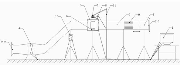
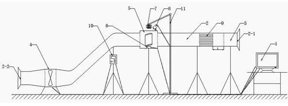
[0014] Such as figure 1 As shown, the flow field display experimental device in the present invention includes a computer 1, a pipeline 2, a tracer gas generator 3, an axial flow fan 4, an observation section 5, a model control device 6, a sheet light cutting flow field device 7, and image data Acquisition control device 8 , steady flow tube bundle 9 , fan frequency conversion control device 10 .

[0015] Both ends of the duct 2 are respectively provided with an air inlet 2-1 and an air outlet 2-2. A tracer gas generating device 3 is arranged in the pipeline 2 close to the air inlet 2-1; an axial flow fan 4 is arranged in the pipeline 2 close to the air outlet 2-2. An observation section 5 is arranged on the pipeline 2 between the tracer gas generator 3 and the axial flow fan 4 . A model control device 6 is arranged in the observation section 5 ; a...


PUM


Abstract

The invention discloses an experimental device for a flow field display. An air inlet and an air outlet are arranged at two ends of a pipeline respectively; a trace gas generating device is arranged in the pipeline and is close to the air inlet; an axial-flow fan is arranged in the pipeline and is close to the air outlet; an observation section is arranged on the pipeline with the trace gas generating device and the axial-flow fan; a model control device is arranged in the observation section; a laser sheet cutting flow field device and an image data acquisition control device are arranged above the observation section; a steady flow tube bundle is arranged in the pipeline between the trace gas generating device and the observation section; a computer is connected with the model control device, the image data acquisition control device and the axial-flow fan through data transmission lines; and a fan frequency conversion control device is connected between the computer and the axial-flow fan. The experimental device is simple and convenient in control, acquires reliable experimental data and is used for qualitative experimental research for a flow field.

Description

technical field [0001] The invention relates to an experimental device, in particular to a flow field display experimental device for qualitative experimental research on flow field. Background technique [0002] Fluid flow is a very complex process, and many flow laws need to be studied. If only mathematical analysis is used, it is difficult to obtain correct results in most cases, but must rely on experiments to explore laws, verify theories, and solve practical problems in production. Flow field display and flow field simulation are two core tasks in the development of fluid mechanics. The flow field display technology is to better intuitively understand the distribution of the entire flow field, grasp the flow characteristics, and help establish theoretical analysis models. Obtain information from flow images, test theoretical analysis results, and discover new phenomena. There are many current flow field display technologies, which can be divided into the first genera...

Claims


Application Information

Patent Timeline
IPC IPC(8): G01M10/00
Inventor 彭维红张昕喆王欢陈宁曹国华晁阳王磊徐勇
Owner CHINA UNIV OF MINING & TECH
Why Eureka
Try Eureka