Switching controller of flyback power converter and its controller and control circuit

A power converter and switching circuit technology, applied in output power conversion devices, DC power input to DC power output, control/regulation systems, etc., can solve large-space, high-output line ripple nonlinear power conversion operations And other issues

Active Publication Date: 2015-09-23
SYST GEN
View PDF3 Cites 1 Cited by
  • Summary
  • Abstract
  • Description
  • Claims
  • Application Information

AI Technical Summary

Problems solved by technology

When there is no filtering effect of the input capacitor 36, the pulsating DC input voltage V IN Will result in higher output line ripple and non-linear power conversion operation
Furthermore, the input capacitor 36 typically takes up a considerable amount of space in the power converter

Method used


Image

  • Switching controller of flyback power converter and its controller and control circuit
  • Switching controller of flyback power converter and its controller and control circuit
  • Switching controller of flyback power converter and its controller and control circuit

Examples


Embodiment Construction

[0121] In order to make the above-mentioned objects, features and advantages of the present invention more clearly understood, a preferred embodiment is exemplified below and described in detail in conjunction with the accompanying drawings.

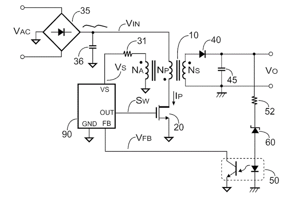
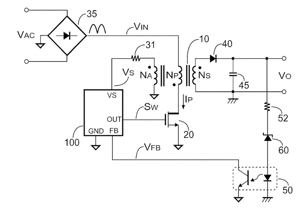
[0122] Figure 1B A flyback power converter according to an embodiment of the present invention is shown. Figure 1A and Figure 1B The only difference is that, Figure 1B The embodiment is to use the switching controller 100 without using Figure 1A input capacitor 36 to perform general output regulation of the power converter.

[0123] The output power P of the flyback power converter O can be expressed as:

[0124] P O = V O × I O = V IN 2 × T ...


PUM


Abstract

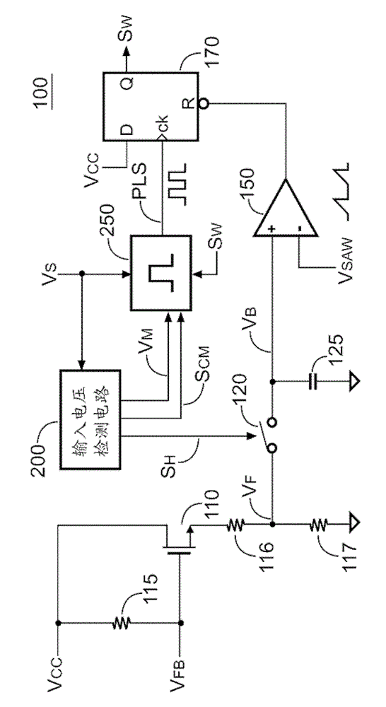
The present invention proposes a switching controller of a flyback power converter. The switching controller includes a switching circuit, a sample-and-hold circuit, a voltage detection circuit, an oscillation circuit, and a comparator. The voltage detection circuit generates a holding signal when a level of an input voltage of the flyback power converter is lower than a low-threshold. The oscillation circuit limits the maximum frequency of switching signal. The maximum frequency is increased in response to a decrement of a modulation signal. The modulation signal correlated with a level of the input voltage is used to generate a control signal when the level of the input voltage is lower than an ultra-low-threshold. The control signal is enabled to operate the flyback power converter in continuous current mode operation. Therefore, an input capacitor can be eliminated and manufacturing cost is saved.

Description

technical field [0001] The present invention relates to a power converter, in particular to a switching control circuit of a flyback power converter. Background technique [0002] Figure 1A is a known flyback power converter. The power converter includes a bridge rectifier 35, an input capacitor 36, a controller 90, a transformer 10, a power transistor 20, a sense resistor 31, a rectifier 40, an output capacitor 45 and a secondary side feedback circuit. Transformer 10 includes a primary side coil N P , Secondary side coil N S and auxiliary coil N A . The secondary side feedback circuit includes a resistor 52 , a Zener diode (as a voltage regulator) 60 , and an optocoupler 50 . The bridge rectifier 35 supplies an alternating current (AC) input voltage V AC Converted to a pulsating direct current (DC) input voltage V IN . This input voltage V IN is also filtered by the input capacitor 36 to a near DC input voltage V IN , which has only relatively small ripples. The...

Claims


Application Information

Patent Timeline
Patent Type & Authority Patents(China)
IPC IPC(8): H02M3/335
CPCH02M2001/0022H02M3/33507H02M1/0022
Inventor 杨大勇林立林昭志
Owner SYST GEN
Why Eureka
Try Eureka