
Longitudinal angle rotation mechanism for mechanical arm

A technology of rotating mechanisms and manipulators, applied in the field of manipulators, can solve problems such as simplicity and structure that have not yet been seen, and achieve the effects of convenient manufacturing, concise overall structure, and quick assembly

Inactive Publication Date: 2012-08-08
CHANGSHU HUIYI MECHANICAL&ELECTRICAL CO LTD
View PDF6 Cites 0 Cited by
  • Summary
  • Abstract
  • Description
  • Claims
  • Application Information

AI Technical Summary

Problems solved by technology

However, in the published Chinese patent literature, there is no technical revelation of the longitudinal angle rotation mechanism of the manipulator with simple structure, controllable rotation angle and adjustable rotation angle.

Method used


Image

  • Longitudinal angle rotation mechanism for mechanical arm
  • Longitudinal angle rotation mechanism for mechanical arm
  • Longitudinal angle rotation mechanism for mechanical arm

Examples


Embodiment

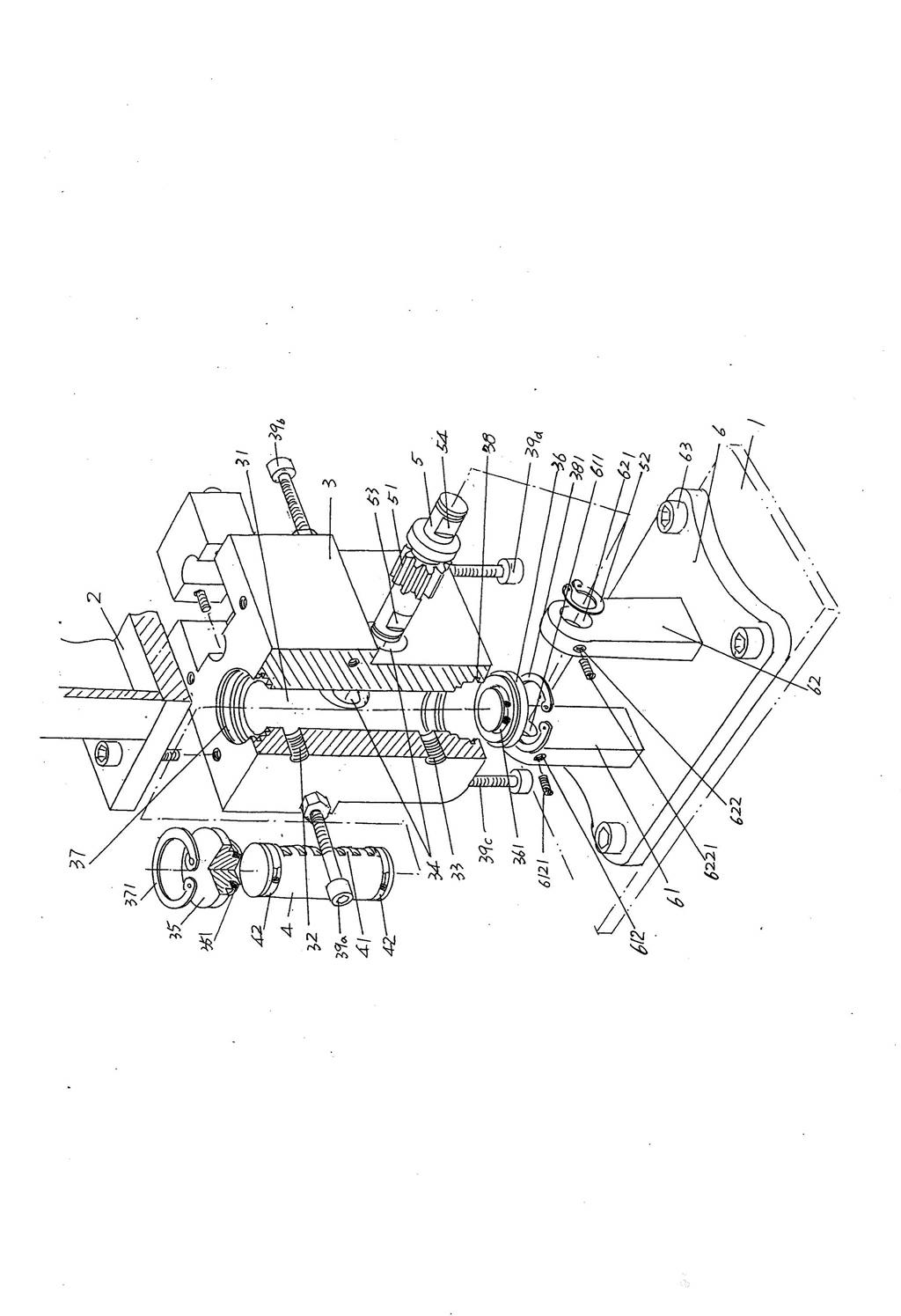
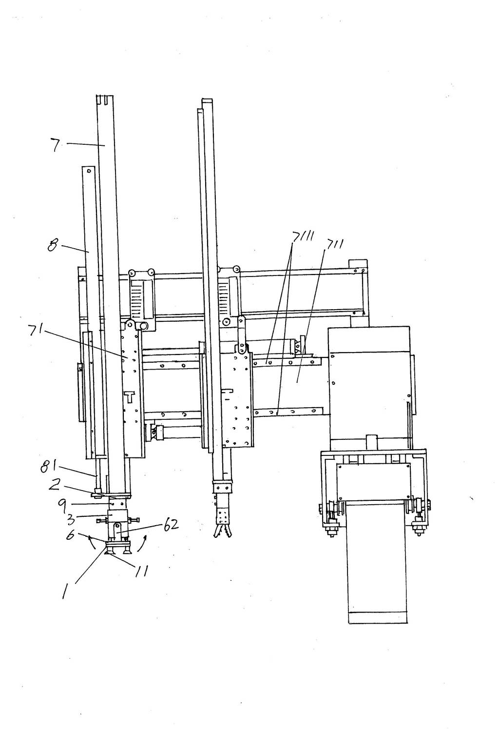
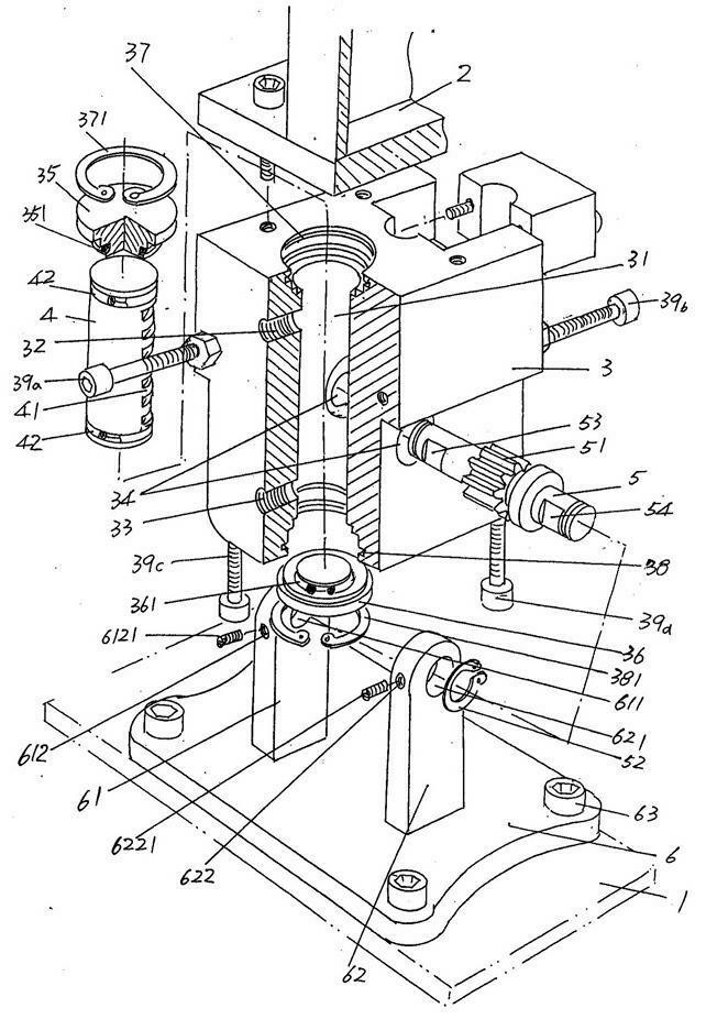
[0021] See figure 1 , the suction cup 1 and the slide bar base 2 of the manipulator are given, and the longitudinal angle rotation mechanism for rotating the suction cup 1 is located between the suction cup 1 and the slide bar base 2 .

[0022] The preferred but not limited longitudinal angular rotation mechanism includes a cylinder block 3, a piston 4, a gear shaft 5 and a rotary seat 6. The cylinder block 3 can also be referred to as a cylinder body (hereinafter the same) through the fixing screw holes provided on it and the fixing screws It is fixed with the aforementioned slider seat 2. The height direction of this cylinder base 3 is processed with a cylinder cavity 31, and one end of the cylinder cavity 31, that is, the upper end of the position shown in the figure, is equipped with a first cylinder head 35, and the other end, that is, the lower end of the position shown in the figure, is equipped with a second cylinder. Cylinder cover 36, and a first limiter groove...


PUM


Abstract

The invention relates to a longitudinal angle rotation mechanism for a mechanical arm, belonging to the technical field of mechanical arms. The mechanical arm comprises a sucking disc and a sliding rod seat. The longitudinal angle rotation mechanism comprises a first cylinder seat forming a cylinder cavity, a piston, a gear shaft and a revolving seat, wherein the upper end at one side of the cylinder seat is provided with a first adaption hole, while the lower end is provided with a second adaption hole, and a gear shaft hole is formed in the cylinder seat; the piston is arranged in the cylinder cavity, and a rack is formed on the wall body at one side of the piston; the first adaption hole corresponds to one end part of the piston, and the second adaption hole corresponds to the other end part of the piston; the gear shaft is arranged in the gear shaft hole, and a gear is formed on the gear shaft; the revolving seat is fixed with the sucking disc, and a first connecting seat and a second connecting seat are fixed at one side of the revolving seat; one end of the gear shaft is supported on the first connecting seat, while the other end is supported on the second connecting seat; and a first limit bolt and a second limit bolt are arranged on the cylinder seat. The longitudinal angle rotation mechanism has the advantages of simple structure, convenience in manufacturing and quick assembly; the sucking disc is driven to rotate by the gear shaft through the revolving seat; and the rotation angle of the sucking disc can be controlled.

Description

technical field [0001] The invention belongs to the technical field of manipulators, and in particular relates to a longitudinal angle rotation mechanism of a manipulator. Background technique [0002] The concept of a manipulator is well known, and it has the function of imitating human claws and arms to complete certain actions. It is an automatic operating device used to grab, carry objects or operate tools according to a fixed program. It can replace the heavy lifting of people. Labor to realize the mechanization and automation of production. In particular: because it can work in a harmful operating environment to protect personal safety, it is widely used in machinery manufacturing, metallurgy, electronics, light industry and even atomic energy and other fields. [0003] The manipulator is mainly composed of a hand (the industry is accustomed to call it a claw) and a motion mechanism. The hand is a part used to grasp the workpiece (or tool), and has various structural...

Claims


Application Information

Patent Timeline
IPC IPC(8): B25J9/02
Inventor 朱建惠
Owner CHANGSHU HUIYI MECHANICAL&ELECTRICAL CO LTD
Learn More