
Electric pum

A technology of electric pumps and pump chambers, which is applied in the direction of pumps, pump devices, pump components, etc., and can solve the problem of difficult fluids being sucked into the pump chamber

Inactive Publication Date: 2012-08-08
AISAN IND CO LTD
View PDF14 Cites 3 Cited by
  • Summary
  • Abstract
  • Description
  • Claims
  • Application Information

AI Technical Summary

Problems solved by technology

Therefore, when the suction port is formed to extend in a direction perpendicular to the rotation axis, it is difficult to suck the fluid into the pump chamber
Therefore, it is difficult to form the suction port so as to extend in the direction perpendicular to the rotation axis

Method used


Image

  • Electric pum
  • Electric pum
  • Electric pum

Examples


Embodiment 1

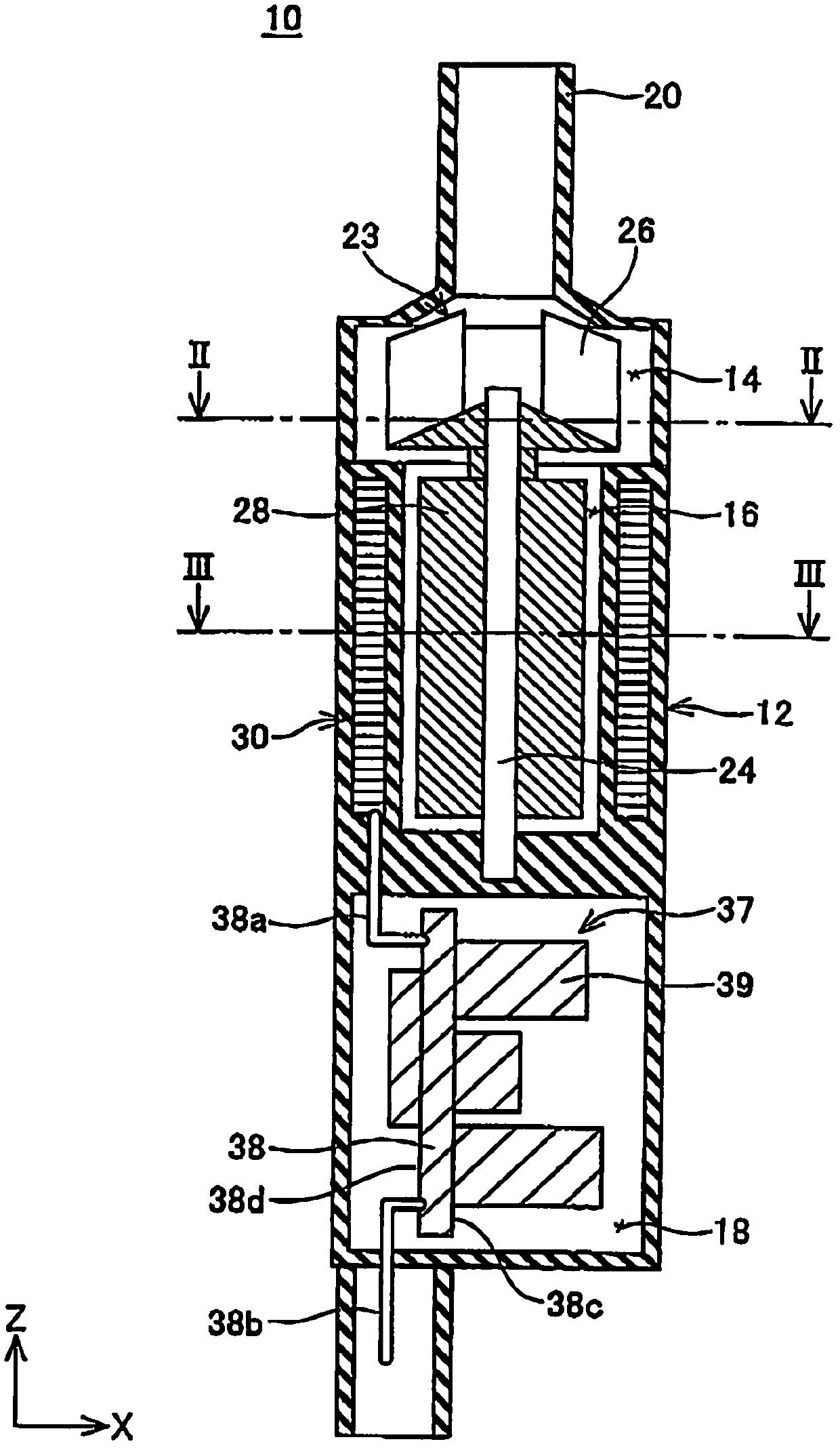
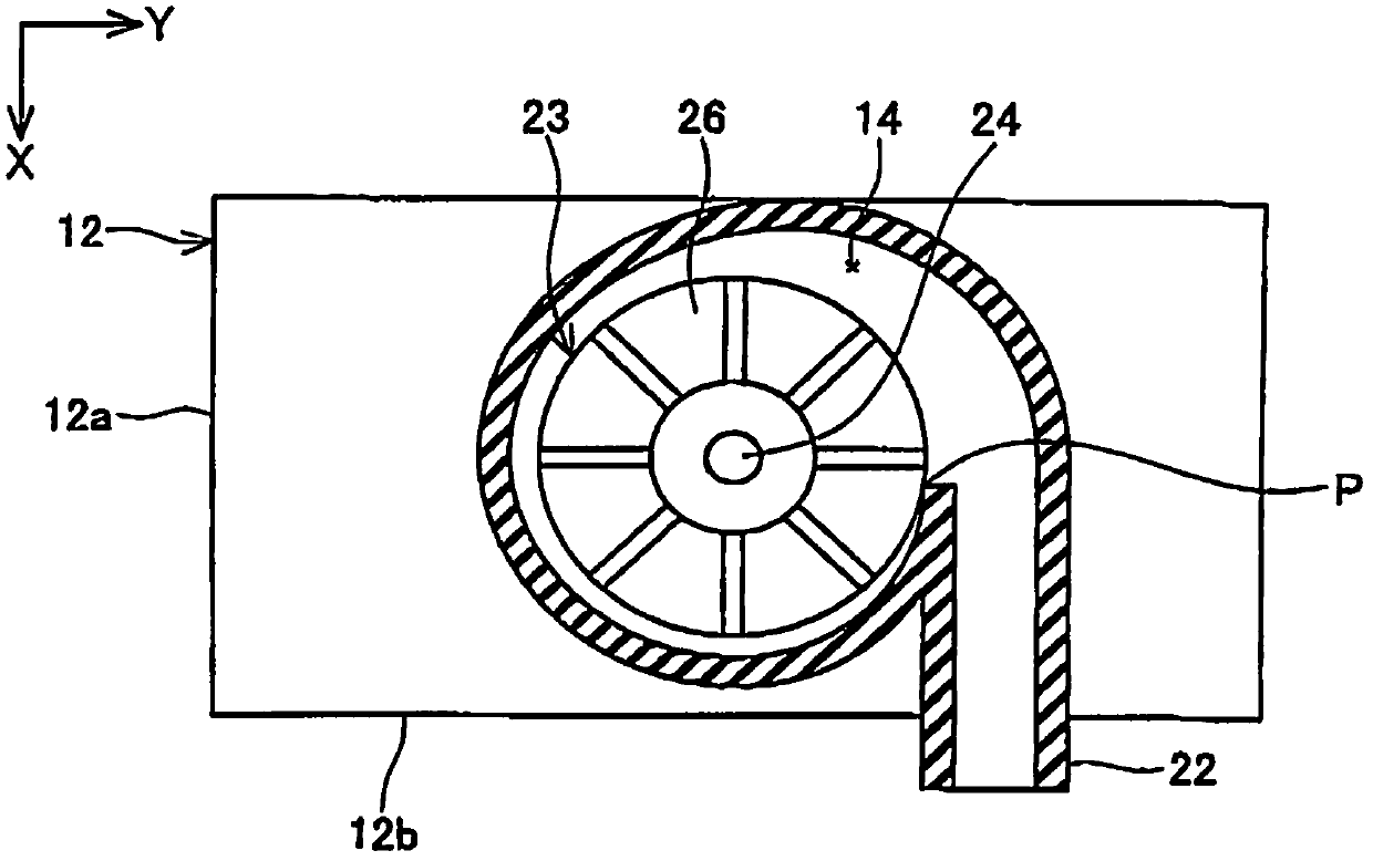
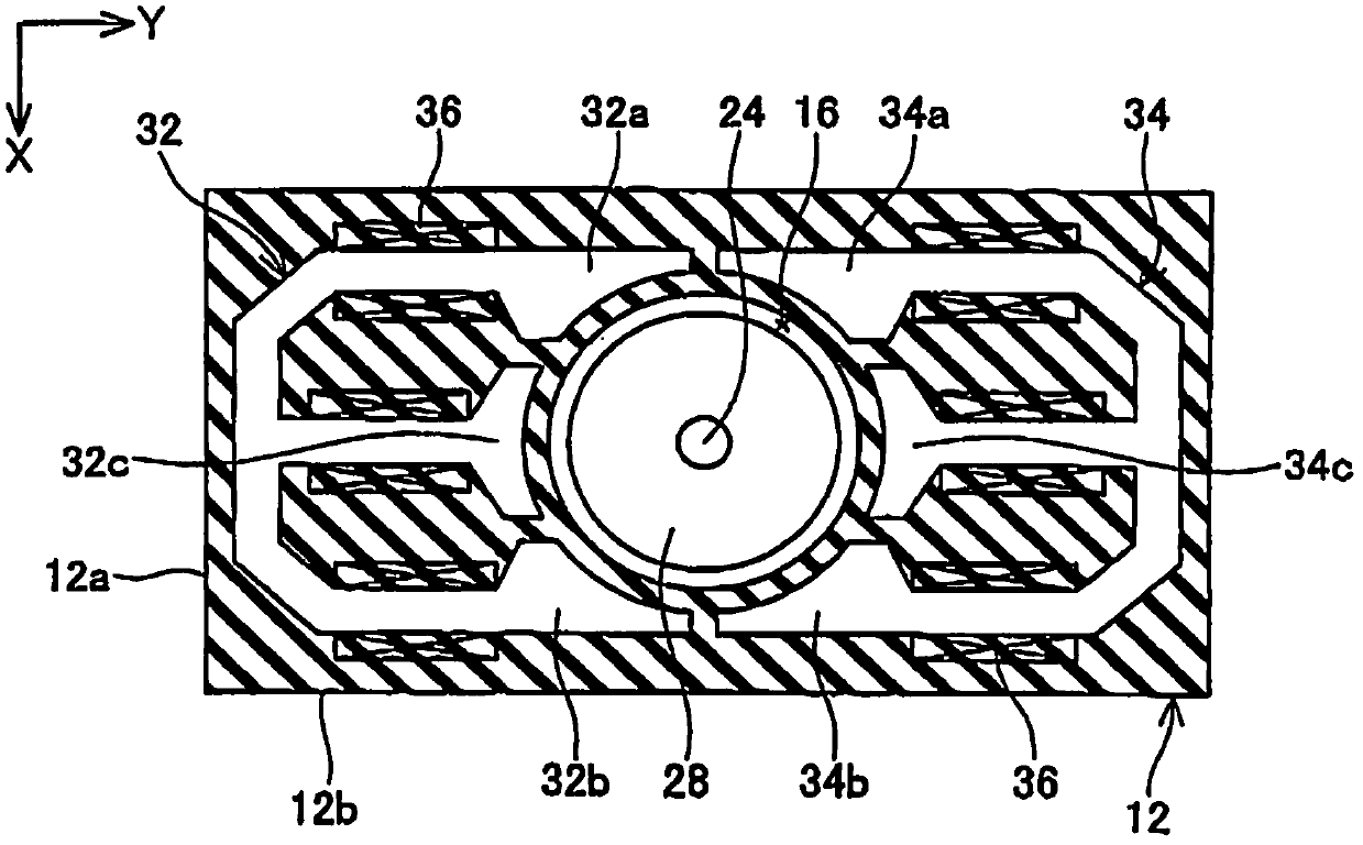
[0047] The electric pump 10 of Embodiment 1 is provided in an engine room of an automobile, and is used for circulating cooling water for cooling an engine, an inverter, and the like. Such as figure 1 As shown, the electric pump 10 includes a casing 12 , a fixed shaft 24 , a rotating body 23 and a stator 30 .

[0048] Three spaces of a pump chamber 14 , a motor chamber 16 , and a circuit chamber 18 are formed in the housing 12 . The pump chamber 14 is formed in the upper portion of the housing 12 . A suction port 20 and a discharge port 22 formed on the housing 12 (in figure 2 Indicated) is connected to the pump chamber 14. The suction port 20 is connected to the upper end of the pump chamber 14 . The suction port 20 extends in the direction in which the rotation axis of the rotating body 23 extends (ie, the z direction). Such as figure 2 As shown, the discharge port 22 is connected to the outer periphery of the pump chamber 14 . The discharge port 22 extends in a ta...


PUM


Abstract

The invention provides an electric pump improving the installation efficiency of the electric pump. The electric pump is provided with motor parts (28, 32, 34, 36), an impeller driven by the motor parts for rotating, a pump chamber used for receiving the impeller. The rotary shafts of the motor parts and the pump chamber are arranged along a rotary shaft of the impeller. The electric pump is also provided with a suction inlet used for suctioning liquid into the pump chamber and a discharge port used for discharging liquid in the pump chamber. The suction inlet and the rotary shaft extend in parallel. On the other hand, the discharge port (22) extends along a direction perpendicular to the rotary shaft. The shape of a cross section of the motor parts (28, 32, 34, 36) which are perpendicular to the rotary shaft is in a flat shape.

Description

technical field [0001] The invention discloses an electric pump. Background technique [0002] There is known an electric pump including a motor unit and a pump unit driven by the motor unit. In such an electric pump, the impeller housed in the pump chamber is rotationally driven by the motor unit. The pump chamber and the motor unit are arranged along the rotating shaft of the impeller (hereinafter, sometimes simply referred to as the rotating shaft), and the output of the motor unit is directly transmitted to the impeller. The above-mentioned electric pump is often installed in a limited space, and thus the size of the electric pump has been reduced in various ways. For example, in the electric pump described in Patent Document 1, the fixed iron core of the motor part is made into a fixed iron core without a coil end (coil end), and the motor part is shortened in the direction of the rotation axis of the impeller, so that the electric pump is improved. miniaturization. ...

Claims


Application Information

Patent Timeline
Patent Type & Authority Applications(China)
IPC IPC(8): F04D13/06F04D29/42F04D29/00
CPCF04D13/064
Inventor 池谷昌纪杉本笃
Owner AISAN IND CO LTD
Learn More