Concentration control apparatus and material gas supply system

a control apparatus and gas supply technology, applied in the direction of container filling under pressure, container discharging methods, transportation and packaging, etc., can solve the problems of increasing the size of the apparatus itself, increasing the length of the respective pipe, increasing the pressure drop of the entire apparatus, etc., to improve responsiveness, shorten the piping, and reduce the effect of maintainability

Active Publication Date: 2019-03-21
HORIBA STEC CO LTD
View PDF11 Cites 1 Cited by
  • Summary
  • Abstract
  • Description
  • Claims
  • Application Information

AI Technical Summary

Benefits of technology

[0035]According to the present invention configured as described above, a concentration control apparatus that, without reducing maintainability, can shorten piping to improve responsiveness can be provided. Also, according to the present invention, a concentration control apparatus that, while integrating respective pipes, can surely heat a pipe (flow path) requiring heating can be provided.

Problems solved by technology

However, although the conventional concentration control apparatus has a high degree of design freedom because the respective pipes and the respective devices can be freely arranged on the panel, there are problems that the total length of the respective pipes increases, and along with the increase, the pressure drop of the entire apparatus increases and the size of the apparatus itself increases.
Further, when the pipe extending from the storage tank to the deposition chamber elongates, there is also a problem of deterioration in responsiveness.
However, when attempting to integrate the entire apparatus in order to respond to the requirements, the respective pipes are closely packed, and along with this, there is a problem of being unable to install a heater for a pipe requiring heating.

Method used


Image

  • Concentration control apparatus and material gas supply system
  • Concentration control apparatus and material gas supply system
  • Concentration control apparatus and material gas supply system

Examples


first embodiment

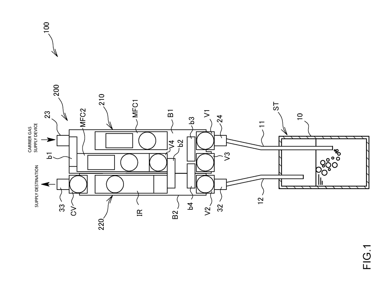
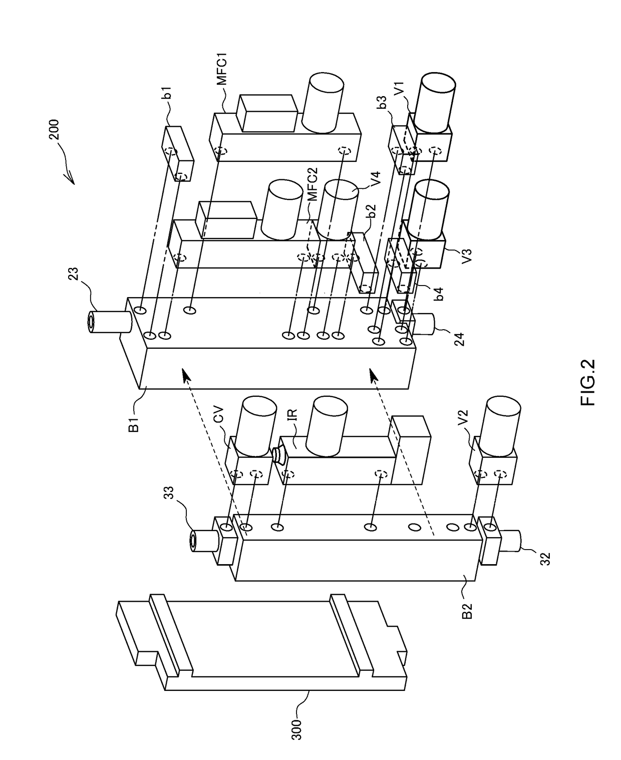
[0054]As illustrated in FIG. 1, a material gas supply system 100 using a concentration control apparatus according to the present invention includes: a storage tank ST for storing a material; and the concentration control apparatus 200 connected to the storage tank ST. In addition, in the present embodiment, the concentration control apparatus 200 is arranged above the storage tank ST, and installed on an installation site such as an unillustrated panel or wall via a heat insulating block 300 (see FIG. 2).

[0055]The storage tank ST includes: a tank main body 10 for storing the material; an introduction pipe 11 for introducing carrier gas into the tank main body 10; and a lead-out pipe 12 for leading out mixed gas consisting of the carrier gas and the material gas from the tank main body 10.

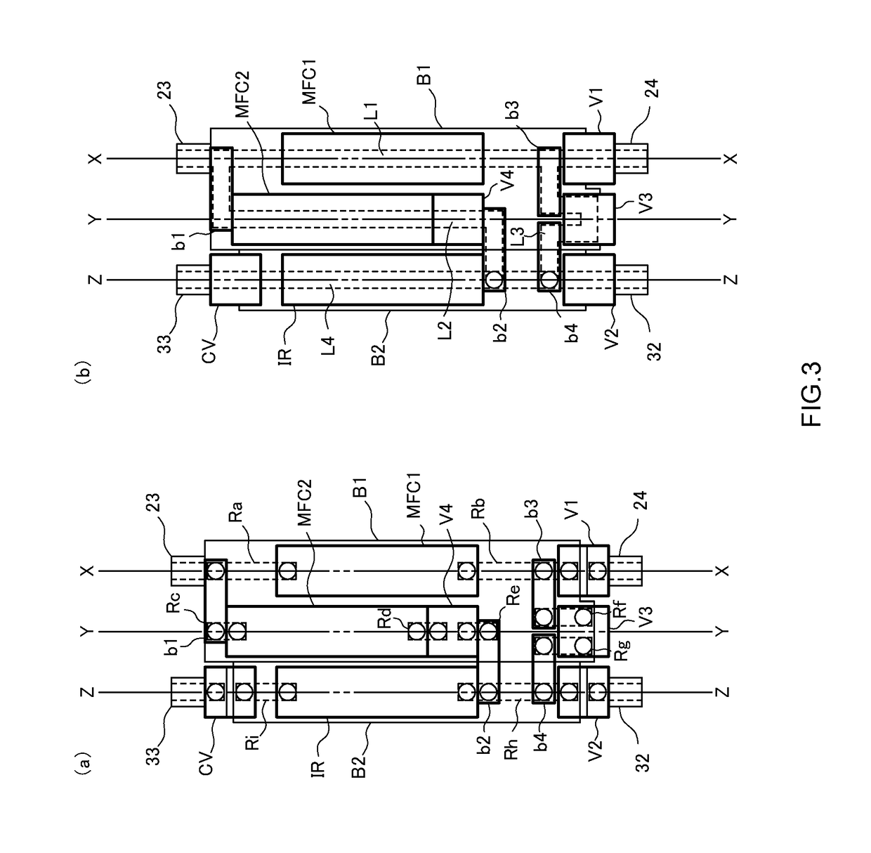
[0056]As illustrated in FIGS. 1 and 2, the concentration control apparatus 200 includes: a first unit 210 connected to the introduction pipe 11 and having a function of controlling the flow rate of...

second embodiment

[0093]The present embodiment is a variation of the concentration control apparatus 200 according to the first embodiment, and is one in which an internal pressure rise prevention function is added to the concentration control apparatus 200 illustrated in FIG. 9. Specifically, as illustrated in FIG. 11, the concentration control apparatus 200 according to the present embodiment is one configured such that the concentration control apparatus 200 illustrated in FIG. 9 is further installed with: a first pressure sensor P1 on the downstream side of the flow rate controller MFC1 in the carrier gas flow path L1; and a second pressure sensor P2 on the downstream side of the flow rate controller MFC 2 in the first bypass flow path L2. More specifically, the first pressure sensor P1 is installed on the upper stream side than the first opening / closing valve V1 in the carrier gas flow path L1, and the second pressure sensor P2 is installed on the upper stream side than the fourth opening / closin...

third embodiment

[0097]The present embodiment is a variation of the concentration control apparatus 200 according to the first embodiment, and one configured such that a backflow prevention function is added to the concentration control apparatus 200 illustrated in FIG. 9. Specifically, as illustrated in FIG. 12, the concentration control apparatus 200 according to the present embodiment is one configured such that the concentration control apparatus 200 illustrated in FIG. 9 is further installed with: a pressure sensor P1 on the downstream side of the flow rate controller MFC1 in the carrier gas flow path L1 and on the upper stream side than the first opening / closing valve V1; a third pressure sensor P3 on the lower stream side than the first opening / closing valve V1; and a second pressure sensor P2 on the downstream side of the flow rate controller MFC2 in the first bypass flow path L2 and on the upper stream side than the fourth opening / closing valve V4.

[0098]In addition, the concentration contro...


PUM

PropertyMeasurementUnit
concentrationaaaaaaaaaa
flow rateaaaaaaaaaa
concentration detectoraaaaaaaaaa

Abstract

Provided is a concentration control apparatus that, without reducing maintainability, can shorten piping to improve responsiveness. The concentration control apparatus is one adapted to introduce carrier gas into a storage tank storing a material, and control the concentration of material gas that is led out of the storage tank as mixed gas with the carrier gas and results from vaporization of the material. Also, the concentration control apparatus includes: a first unit that controls the flow rate of the carrier gas to be introduced into the storage tank; and a second unit that detects the concentration of the material gas led out of the storage tank.

Description

TECHNICAL FIELD[0001]The present invention relates to a concentration control apparatus and a material gas supply system.BACKGROUND ART[0002]In a semiconductor manufacturing process, when supplying material gas stored in a storage tank to a deposition chamber (chamber), a concentration control apparatus that introduces carrier gas supplied from a carrier gas supply device into the storage tank, and while regulating the concentration of the material gas led out of the storage tank together with the carrier gas, supplies both of the gases to the deposition chamber (chamber) is used.[0003]For example, as disclosed in Patent Literature 1, a conventional concentration control apparatus employs a configuration adapted to, on a panel installed above a storage tank, fix respective pipes such as a pipe extending from a carrier gas supply device to the storage tank and a pipe extending from the storage tank to a deposition chamber, as well as fix respective devices such as mass flow controlle...

Claims


Application Information

Patent Timeline
Patent Type & Authority Applications(United States)
IPC IPC(8): C23C14/54
CPCC23C14/548F17C5/06F17C13/02F17C13/04F17D1/02F17D3/01F17C2221/031C23C16/4481C23C16/45561H01L21/67017H01L21/67242H01L21/67098Y10T137/2509
Inventor SHIMIZU, TORUMINAMI, MASAKAZU
Owner HORIBA STEC CO LTD
Why Eureka
Try Eureka