
Automatic underground water pressure control device suitable for underground structure and construction mode

A technology of underground structure and groundwater pressure, applied in basic structure engineering, separation methods, chemical instruments and methods, etc., can solve the problems of high cost, settlement of surface buildings, and large impact on the surrounding environment, and achieves large filtering area and high security. The effect of structural safety

Pending Publication Date: 2021-08-03
CHINA RAILWAY DESIGN GRP CO LTD
View PDF0 Cites 1 Cited by
  • Summary
  • Abstract
  • Description
  • Claims
  • Application Information

AI Technical Summary

Problems solved by technology

When the buried depth of the bottom plate of the underground structure is lower than the groundwater level in the area, the underground structure will be affected by the buoyancy of the groundwater. Conventional measures include setting up anti-floating piles, anti-floating anchors, pressure, and water discharge. For safety, it is necessary to consider the possible highest water level in the service life of the structure. Since the highest water level in the service life is a short-term working condition and a low-probability event, the design of anti-floating measures is often relatively conservative and economical.
[0003] In addition, many underground structures face problems such as overburden unloading during the use phase due to ground planning adjustments, urban renewal, etc., but such working conditions were not considered in the design, and large-scale precipitation is required, which has a great impact on the surrounding environment, and may even Cause the risk of subsidence of the surface buildings; if this short-term working condition is considered in the design, more measures need to be added, which will increase the cost greatly

Method used


Image

  • Automatic underground water pressure control device suitable for underground structure and construction mode
  • Automatic underground water pressure control device suitable for underground structure and construction mode

Examples


Embodiment Construction

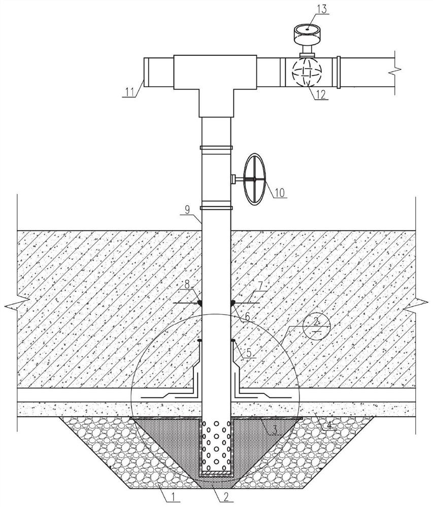
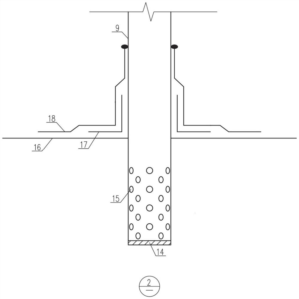
[0019] Such as figure 1 As shown in or 2, the present invention is an automatic control underground water pressure device suitable for underground structures, comprising a steel pipe 9, the bottom of the steel pipe 9 is provided with a back-sealing steel plate 14, and the bottom of the side wall of the steel pipe 9 is uniformly provided with a number of sieve holes 15, and the steel pipe 9 The lower part of the outer wall of 9 is provided with a reinforced waterproof layer, and the joint between the side wall of the steel pipe 9 and the reinforced waterproof layer is provided with a one-component polyurethane sealant 5, and the reinforced waterproof layer includes a flexible waterproof layer 16 and a double-sided self-adhesive adhesive tape 17 and the flexible waterproof reinforcement layer 18, the flexible waterproof layer 16 is wrapped on the outer wall of the steel pipe 9 to ensure that groundwater does not seep out along the connection joint between the drain pipe and the b...


PUM

PropertyMeasurementUnit
diameteraaaaaaaaaa
thicknessaaaaaaaaaa

Abstract

The invention discloses an automatic underground water pressure control device suitable for a underground structure and a construction mode. The automatic underground water pressure control device comprises a steel pipe, wherein a bottom sealing steel plate is arranged at the bottom of the steel pipe, a plurality of screen holes are evenly formed in the bottom of the side wall of the steel pipe, a reinforced waterproof layer is arranged on the lower middle portion of the outer side wall of the steel pipe, the flexible waterproof layer and the flexible waterproof reinforcing layer are fixedly bonded through a double-faced self-adhesive adhesive tape, a water stop flange is arranged in the middle of the steel pipe, a filter screen cleaning plug is installed at the output end of one side of the T-shaped flow dividing pipe, and an automatic pressure relief and drainage ball valve is installed on a pipeline connected with the output end of the other side of the T-shaped flow dividing pipe. According to the automatic underground water pressure control device, a user can reduce anti-floating facilities in the underground structure design stage, and the manufacturing cost is saved; on-demand precipitation is realized in the use stage and the unloading and redevelopment stage, so that the use safety of the underground structure is effectively ensured; and in the construction stage, compensation precipitation can be effectively carried out, and the problems of local precipitation well damage and poor precipitation well effect in the construction stage are solved.

Description

technical field [0001] The invention belongs to the field of underground water pressure control equipment, and in particular relates to an automatic control underground water pressure device and a construction method suitable for underground structures. Background technique [0002] With the continuous acceleration of the urbanization process in our country, the land use in many central urban areas is becoming more and more tense, more and more transportation projects and commercial projects are transferred to the ground, and the buried depth is getting deeper and deeper. The urban underground space ushered in a big development stage. When the buried depth of the bottom plate of the underground structure is lower than the groundwater level in the area, the underground structure will be affected by the buoyancy of the groundwater. Conventional measures include setting up anti-floating piles, anti-floating anchors, pressure, and water discharge. For safety, it is necessary to...

Claims


Application Information

Patent Timeline
Patent Type & Authority Applications(China)
IPC IPC(8): E02D19/06E02D19/10B01D36/02
CPCB01D36/02E02D19/06E02D19/10
Inventor 潘野韩宇张继清吕宝伟王世清曾佳亮张福麟李思于本昌赵志涛李博刘云亮
Owner CHINA RAILWAY DESIGN GRP CO LTD
Learn More