
A method and device for collecting a section of a sediment layer during a mud deposition test

A test process and deposition layer technology, applied in measuring devices, sampling devices, instruments, etc., can solve the problem of inability to accurately carry out cross-sections at different positions, and achieve the effects of equipment safety, accuracy and reliability.

Active Publication Date: 2018-07-24
INST OF ROCK & SOIL MECHANICS CHINESE ACAD OF SCI
View PDF7 Cites 0 Cited by
  • Summary
  • Abstract
  • Description
  • Claims
  • Application Information

AI Technical Summary

Problems solved by technology

The present invention also provides a device for collecting the section of the sedimentary layer during the mud deposition test, which can effectively solve the problem that the current indoor mud deposition test cannot accurately sample sections at different positions

Method used


Image

  • A method and device for collecting a section of a sediment layer during a mud deposition test
  • A method and device for collecting a section of a sediment layer during a mud deposition test
  • A method and device for collecting a section of a sediment layer during a mud deposition test

Examples


Embodiment 1

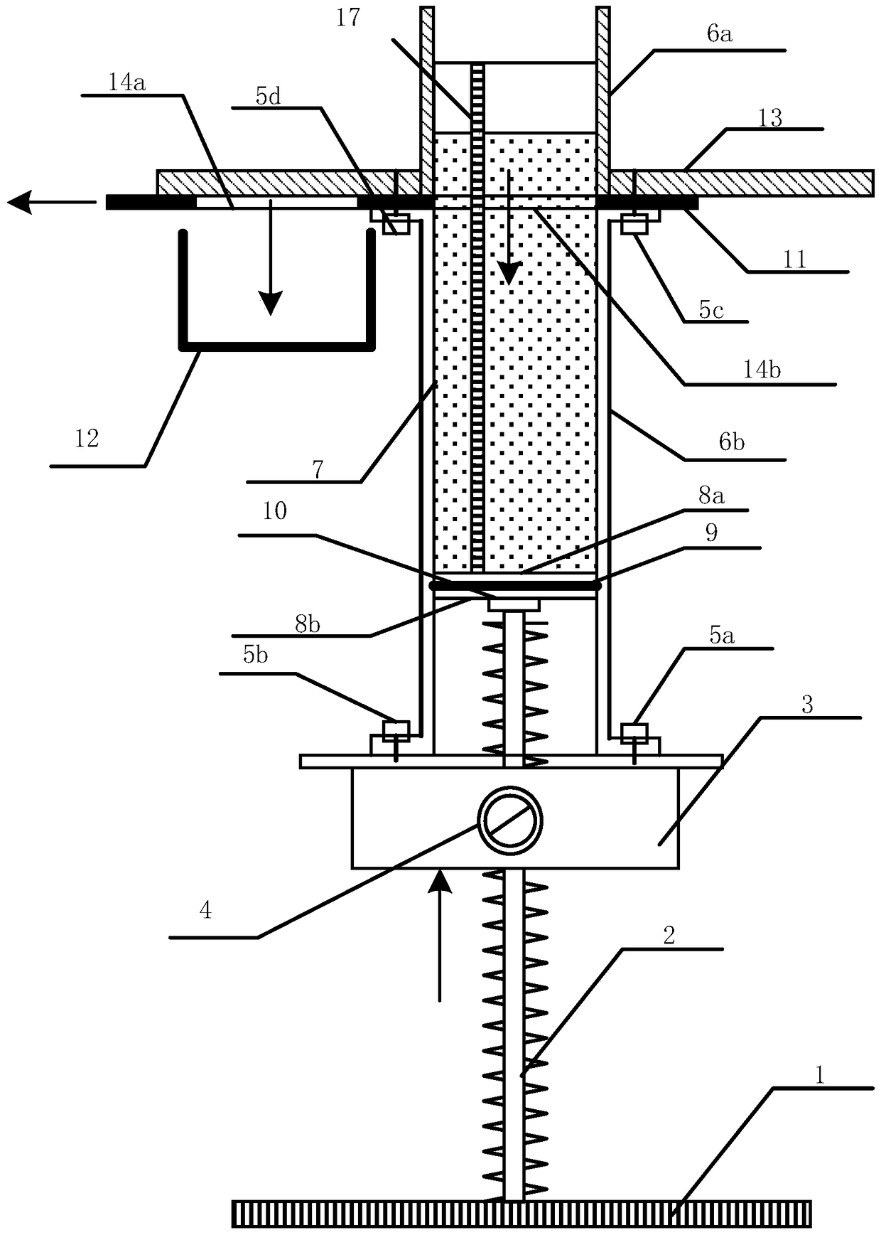
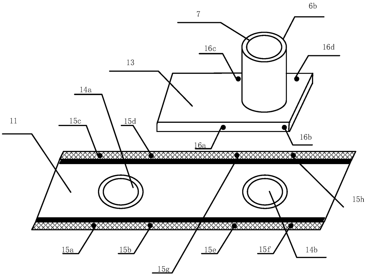
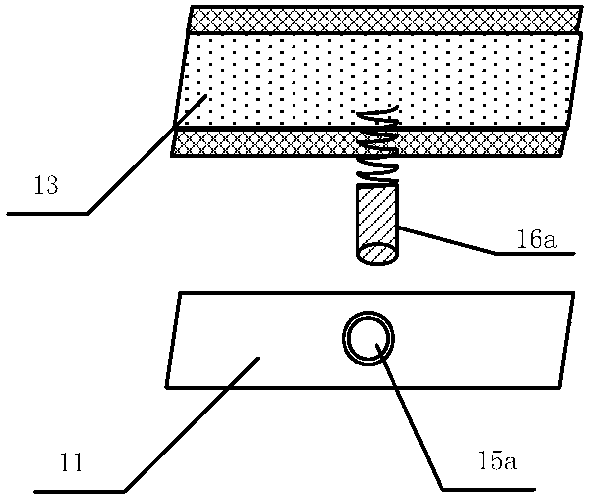
[0049] A device for collecting sediment section sections during a mud deposition test (see Figure 1-Figure 4 ), including a base 1, a spiral lifting rod 2, a transmission gearbox 3, a control valve 4, a first bolt 5a, a second bolt 5b, a third bolt 5c, a fourth bolt 5d, a first outer cylinder 6a, a second outer cylinder 6b, deposition cylinder 7, first upper stopper 8a, second upper stopper 8b, sealing ring 9, steel sheet 10, cutting plate 11, sampling cylinder 12, steel plate 13, first sampling tank 14a, second sampling tank 14b, the first round hole 15a, the second round hole 15b, the third round hole 15c, the fourth round hole 15d, the fifth round hole 15e, the sixth round hole 15f, the seventh round hole 15g, the eighth round hole 15h, The first spring telescopic cap 16a, the second spring telescopic cap 16b, the 3rd spring telescopic cap 16c, the 4th spring telescopic cap 16d and the scale 17, the base 1 is fixed at the bottom of the spiral lifting rod 2, and the speed c...

Embodiment 2

[0069] Since the moving speed of the cutting plate 11 has a great influence on the physical property index of the sample of the collected sediment layer, embodiment 2 adopts the mud with the same water content as that of embodiment 1, and collects the section of the sediment layer at the same time, but uses a different cutting plate 11 Moving speed.

[0070] A method for collecting a section of a sediment layer in a mud deposition test process, comprising the following steps:

[0071] Steps (1) to (3) are the same as in Example 1;

[0072] (4) Collection of sediment section

[0073] Before collecting the deposition layer, the rotary control valve 4 activates the transmission gearbox 3 to make the first upper blocking plate 8a, the second upper blocking plate 8b, the sealing ring 9 and the steel sheet 10 rise in the second outer cylinder 6b, and then push the deposition cylinder 7 Move upwards, observe the scale 17, and stop rotating the control valve 4 when the sampling posi...


PUM

PropertyMeasurementUnit
thicknessaaaaaaaaaa

Abstract

The invention discloses a device for collecting a deposited layer cross section in a mud depositing test process; a base is used for fixing the bottom of a spiral lifting rod; a speed change gear box is erected on the spiral lifting rod, the top of the spiral lifting rod is provided with a deposition cylinder; the outer wall of the deposition cylinder sleeves a second outer cylinder; the second outer cylinder is fixed on the speed change gear box, and a horizontal-sliding cutting board is placed on the top of the second outer cylinder; the cutting board is provided with a first sampling groove and a second sampling groove in the sliding direction; a first outer cylinder and the second outer cylinder are fixed and butted; scales are vertically pasted on the outer walls of the first outer cylinder and the second outer cylinder. At the same time, the invention provides a method for collecting the deposited layer cross section in the mud depositing test process, wherein the method comprises the steps of instrument assembly, mud preparation, depositing test, and deposited layer cross section collection. In the mud depositing test process, any position is selected for nondestructive and repeated collection of the deposited layer cross section, the deposited layer collection precision is improved, and the device and method have the advantages of being safe and reliable, low in construction cost and easy to operate.

Description

technical field [0001] The invention relates to the technical field of collection of sedimentary layer cross sections for indoor mud deposition tests, in particular to a method for collecting sedimentary layer cross sections during mud deposition tests, and also to a device for collecting sedimentary layer cross sections during mud deposition tests. Background technique [0002] With the rapid development of coastal port construction, the scale of dredger land reclamation projects is getting larger and larger, and the sedimentation characteristics of dredger fill mud under its own weight have become the focus of current research. Understanding the sedimentation characteristics of dredger fill mud in still water has important research significance for the design of relevant control parameters for dredger fill engineering design, which can provide reliable technical support for the design and construction of dredge fill engineering. Indoor sedimentation test is an important me...

Claims


Application Information

Patent Timeline
Patent Type & Authority Patents(China)
IPC IPC(8): G01N33/00G01N1/12
Inventor 张先伟杨爱武王韬尹松李锐铎曾志雄
Owner INST OF ROCK & SOIL MECHANICS CHINESE ACAD OF SCI
Learn More