Centrifugal compressor having variable geometry diffuser and method thereof

A centrifugal compressor and diffuser technology, applied in non-variable-capacity pumps, machines/engines, components of pumping devices for elastic fluids, etc., can solve problems such as lack of resistance to vibration and achieve easy connection Effect

Inactive Publication Date: 2012-08-08
SIEMENS AG
View PDF6 Cites 7 Cited by
  • Summary
  • Abstract
  • Description
  • Claims
  • Application Information

AI Technical Summary

Problems solved by technology

However, the device lacks strength against vibration due to its rigid arrangement

Method used


Image

  • Centrifugal compressor having variable geometry diffuser and method thereof
  • Centrifugal compressor having variable geometry diffuser and method thereof
  • Centrifugal compressor having variable geometry diffuser and method thereof

Examples


Embodiment Construction

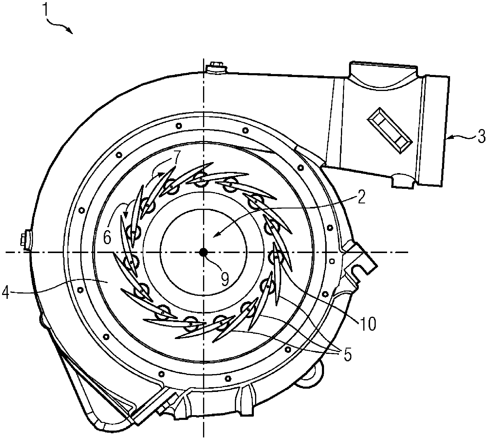
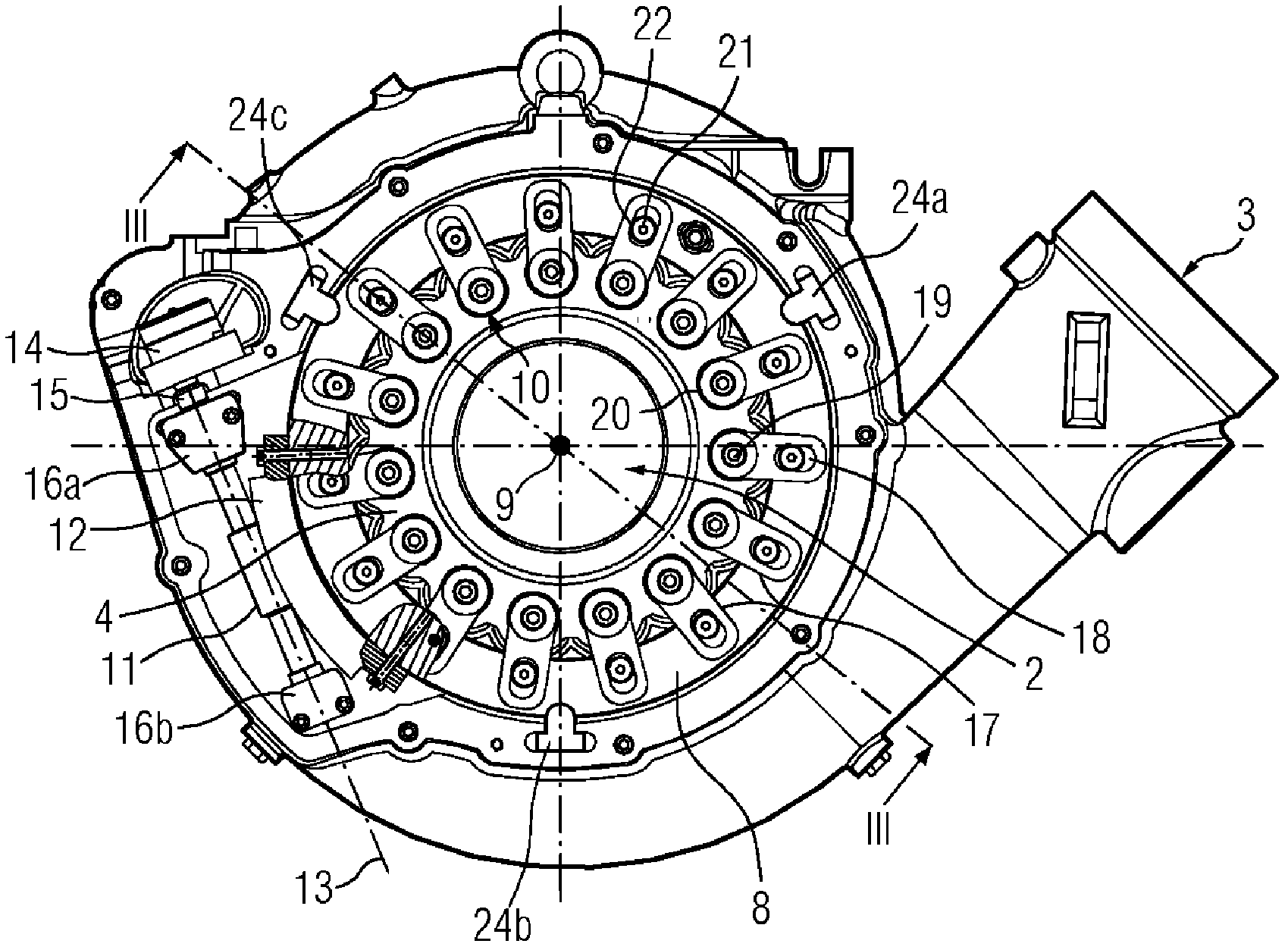
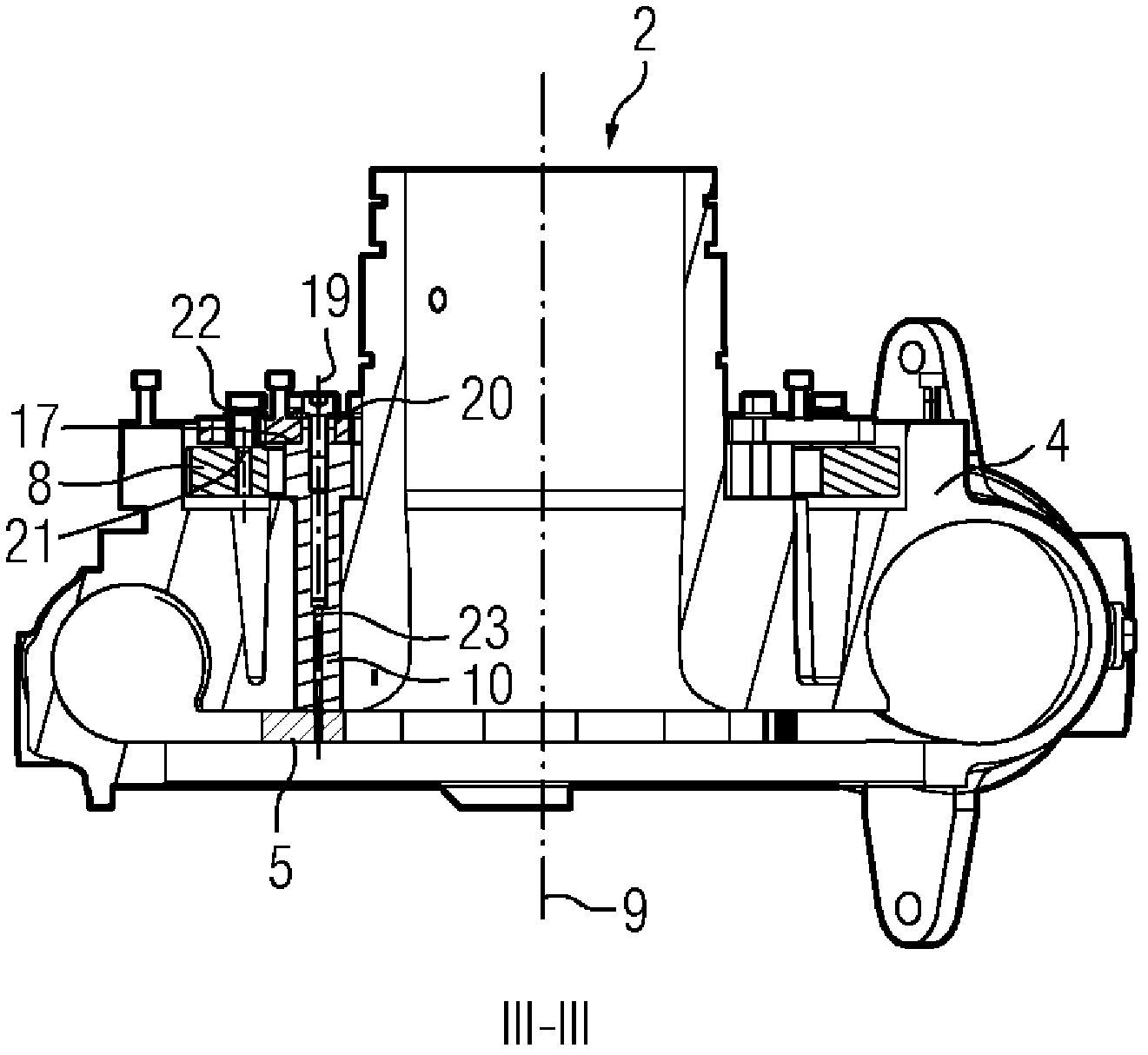
[0018] now refer to figure 1 , figure 1 A rear view of the centrifugal compressor 1 is shown. In operation, compressor 1 receives gas axially through inlet 2 . The gas flowing through the inlet 2 is accelerated by an impeller mounted on a rotor (not shown for clarity), which increases the kinetic energy of the gas. The kinetic energy of the gas is then converted into a pressure increase by diffuser vanes 5 arranged downstream of the impeller. The impeller and diffuser vanes are housed in the volute casing 4 , which direct the gas tangentially flowing from the diffuser towards the compressor outlet 3 .

[0019] The diffuser vanes 5 are arranged in arrays spaced circumferentially around the machine axis 9 . In order to provide a wide operating range, the position of the diffuser vanes 5 can be varied between a maximum volumetric flow setting and a minimum volumetric flow setting. The variable geometry is achieved by pivoting the diffuser vanes 5 to match the discharge angle...


PUM


Abstract

The invention provides a centrifugal compressor having variable geometry diffuser and a method thereof. The centrifugal compressor (1) comprises a plurality of diffuser vanes (5) arranged in a circumferentially spaced array about a machine axis (9). Each diffuser vane (5) is mounted on a respective shaft (10). Each of the shafts (10) is coupled to a ring (8) that is rotatable about the machine axis (9). A worm drive (11,12) is provided that comprises a worm (11) that meshes with a worm gear (12) or a segment of a worm gear (12) mounted along at least a portion of the circumference of the ring (8). A step motor (14) is coupled to the worm (11. The step motor (14) is operable to rotate the worm (11) about a worm axis (13) perpendicular to the machine axis (9), such that the worm drive (11,12) transmits rotational torque from the step motor (14) to said ring (8), to resultantly vary the position of the diffuser vanes (5).

Description

technical field [0001] The present invention relates to centrifugal compressors, and more particularly to centrifugal compressors having vaned diffusers of variable geometry. Background technique [0002] It is well known in the field of rotary compressors that most applications require the reduction of the relatively high velocity of the gas discharged from such a compressor arrangement for subsequent utilization, such as in a gas turbine engine for energy production . In order to realize the conversion of the kinetic energy of the high-speed gas into the pressure increase of the gas, a diffuser is currently used downstream of the compressor to realize the conversion through a diffusion process. [0003] Previously, variable geometry diffusers for centrifugal compressors were thought to be able to provide a wide operating range. Variable geometry is achieved by pivoting the diffuser vanes to match the discharge angle of the airflow from the impeller and by adjusting the m...

Claims


Application Information

Patent Timeline
Patent Type & Authority Applications(China)
IPC IPC(8): F04D29/44
CPCF04D29/462F01D17/165F05D2250/52
Inventor 克劳斯·斯米茨·汉森约根·利奎斯特
Owner SIEMENS AG
Why Eureka
Try Eureka