Method for driving liquid crystal display panel in polarity-reversal mode and apparatus thereof

A liquid crystal display, polarity reversal technology, used in static indicators, instruments, etc., can solve the problems of flicker or crosstalk deterioration, partial brightness, etc., and achieve the effect of reducing flicker and crosstalk phenomenon

Inactive Publication Date: 2012-08-08
BOE TECH GRP CO LTD +1
View PDF5 Cites 39 Cited by
  • Summary
  • Abstract
  • Description
  • Claims
  • Application Information

AI Technical Summary

Problems solved by technology

for figure 1 In b, in the same frame, the data signal of some rows pulls up the voltage Vcom, and some rows pull it down. The process of Vcom being pulled down from top to bottom or from bottom to top will affect the input of the effective voltage of the next row of pixels. like figure 1 As shown in b, the Vcom of the first row is pulled high, and when the signal of the second row of pixels is written, the voltage difference of the pixel voltage of the sub-pixel G relative to Vcom is less than a predetermined value, and the pixel voltage of th...

Method used


Image

  • Method for driving liquid crystal display panel in polarity-reversal mode and apparatus thereof
  • Method for driving liquid crystal display panel in polarity-reversal mode and apparatus thereof
  • Method for driving liquid crystal display panel in polarity-reversal mode and apparatus thereof

Examples


Embodiment 1

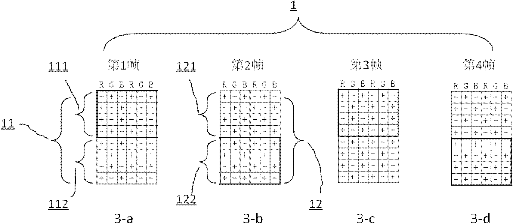
[0046] Figure 3 to Figure 8 Shown is a first embodiment of the invention. image 3 It shows that in the display process of driving the liquid crystal panel, four frames constitute a polarity inversion driving cycle (marked as 1), namely image 3 -a, 3-b, 3-c, 3-d correspond to the polarity arrangement of the first frame, the second frame, the third frame and the fourth frame respectively, wherein the first frame ( image 3 -a) and the third frame ( image 3 -c) has the same polarity arrangement, but the polarity is opposite; the second frame ( image 3 -b) and the fourth frame ( image 3 -d) have the same polarity arrangement but opposite polarity, and image 3 -a and image 3 -b has a different polarity arrangement. At the first frame, as in image 3 -a, the polarity arrangement is repeated in the vertical direction (parallel to the data signal line) with eight rows (marked as 11), in which the first small unit 111 is composed of the first row to the fourth row, and t...

Embodiment 2

[0058] The second embodiment that embodies the technical features of the present invention adopts Figure 9 , Table 3, Table 4, Figure 10 and Figure 11 Be explained. Such as Figure 9 As shown, a polarity inversion driving cycle (marked as 2) consists of four frames, and the periodic polarity arrangements corresponding to the first frame, the second frame, the third frame and the fourth frame correspond to Figure 9 -a, 9-b, 9-c and 9-d, any one of the frames can be used as the starting frame of the polarity inversion driving period. Figure 9 In -a, the polarity arrangement is repeated in the vertical direction (parallel to the data signal line) with a period of 8 rows (marked 21), in which the first small unit 211 is composed of the first row to the fourth row, and the fifth row to the eighth row Rows form the second small unit 212. For the first small unit 211, the polarity arrangement on the same column (such as the red sub-pixel R column) is negative, positive, posi...

Embodiment 3 5

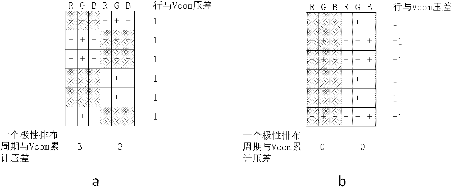
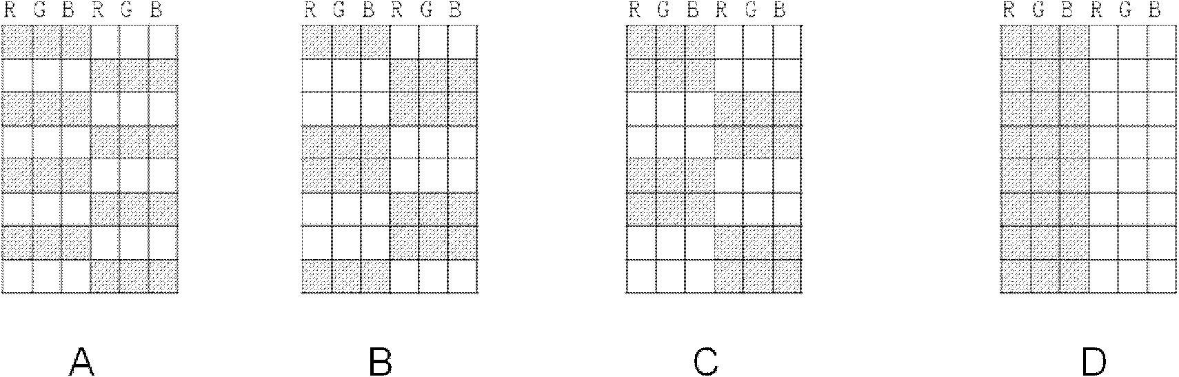
[0068] Figure 12 , Figure 13 and Figure 14 It is the third driving method, the fourth driving method and the fifth driving method listed according to the polarity inversion driving method of the present invention. Regardless of which method, the polarity arrangement of two adjacent frames is different. Similarly, it is not a simple polarity reversal in the prior art. Table 5 provides the third embodiment, the fourth embodiment and the fifth embodiment in the display figure 2 When the evaluation screens A, B, C, and D are shown, within a polarity arrangement period, the difference in the polarity cumulative amplitude of the data signals of two adjacent frames relative to Vcom is different from the polarity cumulative amplitude of Vcom in the existing driving mode As a result of the difference comparison, the polarity cumulative difference between two adjacent frames using the driving method of the present invention is only 8V at most, which is smaller than the 16V of the...


PUM


Abstract

The invention, which relates to the liquid crystal display panel driving technology field, discloses a method for driving a liquid crystal display panel in a polarity-reversal mode and an apparatus thereof. The method comprises the following steps that: four frames form a polarity-reversal driving period and any of the four frames with a polarity arrangement mode can be used as an initial frame; and a displayed image is scanned in the way of a right order or a reversed order of the four frames. Besides, polarity arrangement modes of the first frame and the third frame in the polarity-reversal driving period are identical and the polarities thereof are opposite; polarity arrangement modes of the second frame and the fourth frame are identical and the polarities are opposite; and the polarity arrangement mode of the first frame is different from the one of the second frame. In addition, the invention also provides an apparatus for realizing the method. According to the designed driving scheme, occurrences of scintillation and crosstalk phenomena that occur on a liquid crystal display panel when a certain picture is displayed can be reduced.

Description

technical field [0001] The invention relates to the technical field of liquid crystal display panel driving, in particular to a polarity inversion driving method and device for a liquid crystal display panel. Background technique [0002] With the development of economy and technology, displays, especially liquid crystal flat panel display devices, are becoming more and more popular in computer, mobile device, multimedia and TV display. The coupling of the common electrode causes screen flicker and crosstalk caused by the fluctuation of the common voltage. The driving methods of the current LCD panel mostly adopt the polarity inversion methods of dot inversion, 2-dot inversion, and 1+2 dot inversion. For some special evaluation graphics, if the coupling effect of the data signal to the common electrode is relatively large, the common voltage cannot return to the normal value at the beginning of the next frame, which will cause flickering of the screen or serious crosstalk in...

Claims


Application Information

Patent Timeline
IPC IPC(8): G09G3/36
CPCG09G3/36G09G3/3614G09G2320/0209G09G2320/0247
Inventor 刘金良朱修剑
Owner BOE TECH GRP CO LTD
Why Eureka
Try Eureka