Over-current protection circuit

A technology of overcurrent protection circuit and protection module, which is applied in the direction of emergency protection circuit device, protection reacting to overcurrent, circuit device, etc. It can solve the problems of affecting normal production, high maintenance cost, burning out power drive tube, etc. To achieve the effect of improving labor productivity and reducing labor costs

Active Publication Date: 2012-08-08
SHENZHEN HANDTOP TECH
View PDF5 Cites 21 Cited by
  • Summary
  • Abstract
  • Description
  • Claims
  • Application Information

AI Technical Summary

Problems solved by technology

[0002] The overcurrent protection circuit is one of the most commonly used protection circuits in electronic circuit design. It is mainly to automatically shut off the current output when the load is short-circuited or the current suddenly increases, so as to avoid burning out the power drive tube and causing high maintenance costs. also affect the normal production
[0003] Commonly used over-current protection methods include: 1. Use standard over-current protection devices (such as fuses) directly, and the fuse will be burned after over-current, so you only need to replace the fuse during maintenance, instead of replacing expensive power drive tubes ; 2. Use a self-recovery fuse. This method has a good protective effect on the instantaneous load short circuit, but once the load short circuit time is too long, the self-recovery function of the fuse will start the power drive tube again, and eventually the power drive tube will be damaged. ; 3. The special overcurrent protection circuit designed according to the principle of the self-recovery fuse can be applied in a specific use environment, but they all have a common shortcoming that the protection action is slow and cannot be kept in the protection state, so it cannot be completely avoided. Equipment damage, but only to minimize equipment damage or reduce maintenance costs after equipment damage within a certain range through certain means

Method used


Image

  • Over-current protection circuit
  • Over-current protection circuit
  • Over-current protection circuit

Examples


Embodiment Construction

[0030] The present invention provides an overcurrent protection circuit. In order to make the purpose, technical solution and effect of the present invention clearer and clearer, the present invention will be further described in detail below with reference to the accompanying drawings and examples. It should be understood that the specific embodiments described here are only used to explain the present invention, not to limit the present invention.

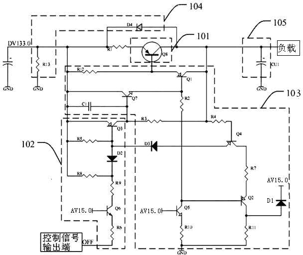
[0031] see figure 1 , the overcurrent protection circuit provided by the present invention includes a switch control module 101 , a software switch protection module 102 and a hardware switch protection module 103 . The input end of the switch control module 101 is connected to the DV133.0 high level, and the output end is connected to the load; the software switch protection module 102 and the hardware switch protection module 103 are connected to the control end of the switch control module 101 . The software switch protection...


PUM


Abstract

The invention discloses an over-current protection circuit, including a switch control module, high and low level states, and software and hardware switch protection modules. An input end and an output end of the switch control module are respectively connected with a high level and a load, the software and hardware switch protection modules are connected with a control end of the switch control module, and the software switch protection module includes a constant current source module. In the over-current protection circuit provided by the invention, output turning-off of the switch control module can be controlled automatically either by the software switch protection module according to the practical running need of a device or by hardware through automatically detecting electric current flowing through a power driving tube. The two protection methods are integrated together, and protection will take effect if either condition is met at any time. The constant current source module will keep an output turning-off state if the load is short-circuited for a long time, and can return back to its normal state once external abnormalities are excluded. Therefore the device can be free of maintenance and manual intervention in operation, which reduces labor cost and greatly improves labor productivity.

Description

technical field [0001] The invention relates to the technical field of overcurrent protection of electronic equipment, in particular to an overcurrent protection circuit. Background technique [0002] The overcurrent protection circuit is one of the most commonly used protection circuits in electronic circuit design. It is mainly to automatically shut off the current output when the load is short-circuited or the current suddenly increases, so as to avoid burning out the power drive tube and causing high maintenance costs. It also affects normal production. [0003] Commonly used over-current protection methods include: 1. Use standard over-current protection devices (such as fuses) directly, and the fuse will be burned after over-current, so you only need to replace the fuse during maintenance, instead of replacing expensive power drive tubes ; 2. Use a self-recovery fuse. This method has a good protective effect on the instantaneous load short circuit, but once the load s...

Claims


Application Information

Patent Timeline
Patent Type & Authority Applications(China)
IPC IPC(8): H02H3/08H02H3/06
Inventor 赵义发
Owner SHENZHEN HANDTOP TECH
Why Eureka
Try Eureka