S-line direct current permanent magnet motor

A permanent magnet motor and coil technology, applied in electrical components, electromechanical devices, magnetic circuit static parts, etc., can solve problems such as limiting the further improvement of permanent magnet motors, and achieve the effect of high efficiency factor and reduced copper consumption

Inactive Publication Date: 2012-08-08
安明武
View PDF0 Cites 3 Cited by
  • Summary
  • Abstract
  • Description
  • Claims
  • Application Information

AI Technical Summary

Problems solved by technology

[0003] As far as the development status of permanent magnet motors is concerned, there is still room for further research on the copper loss and pole efficiency factor of permanent magnet motors, because the existing permanent magnet motors have not made substantial breakthroughs in the innovation of stator structures. The size of the motor stator slot and the structural relationship of the coil limit the further improvement of the permanent magnet motor, and there are many shortcomings. Therefore, further improving the operating efficiency and guarantee factor of the permanent magnet motor and reducing the copper loss of the stator are the structural design of the permanent magnet motor. main subject

Method used


Image

  • S-line direct current permanent magnet motor
  • S-line direct current permanent magnet motor
  • S-line direct current permanent magnet motor

Examples


Embodiment Construction

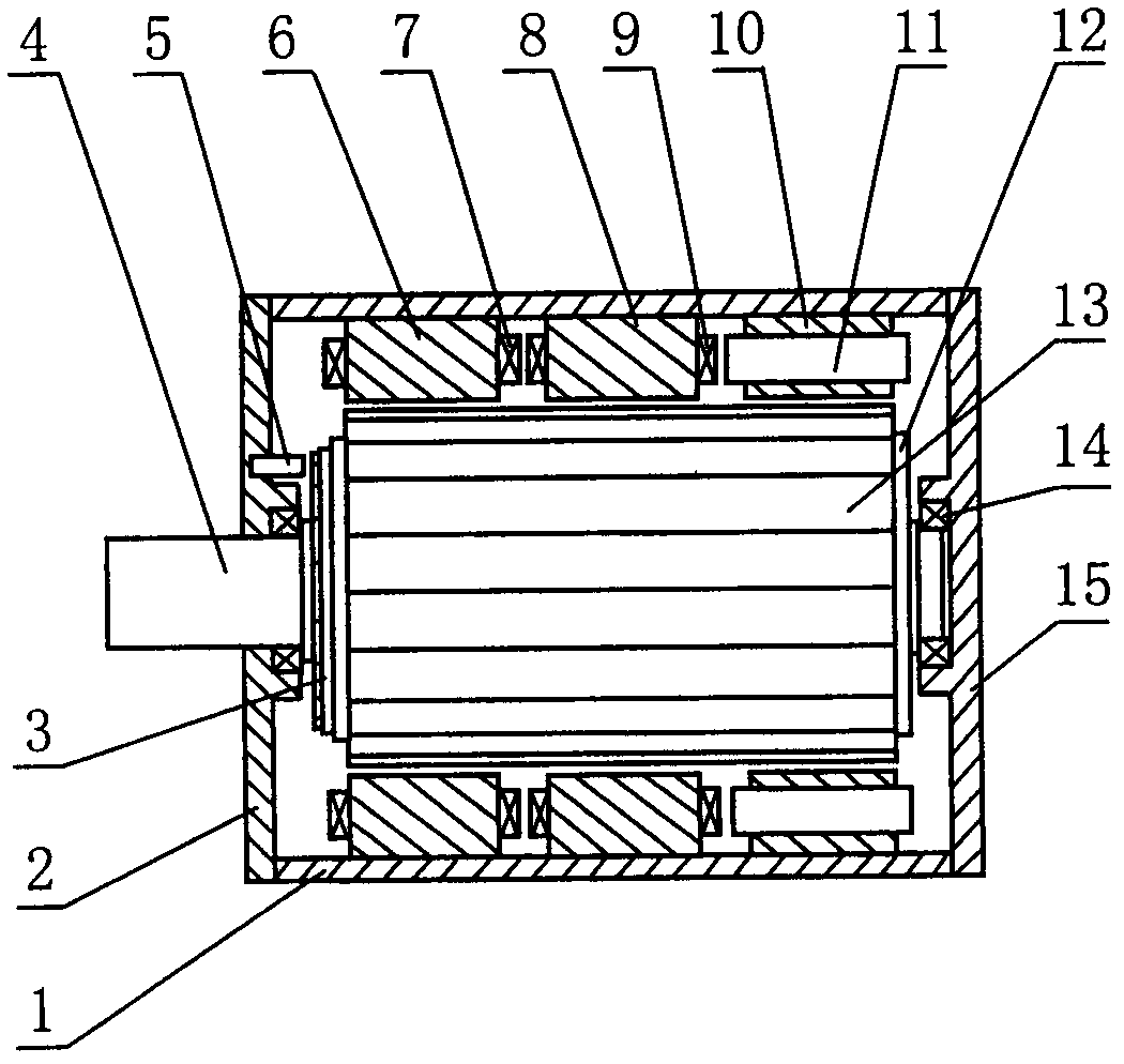
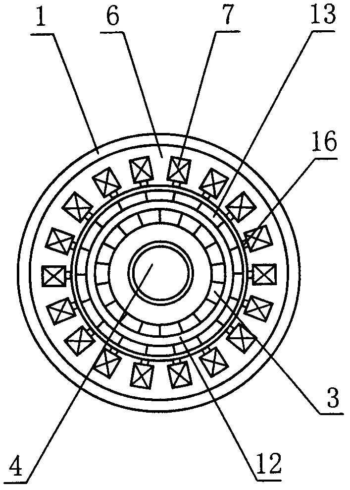
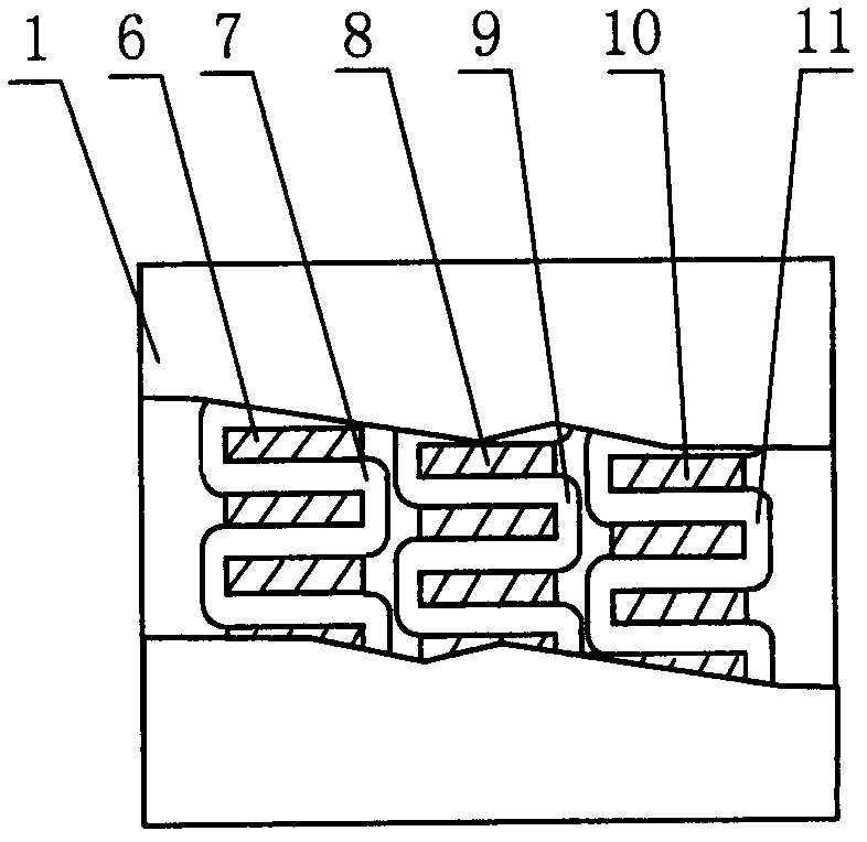
[0024] The present invention consists of a casing 1, a front end cover 2, a magnetic signal disk 3, a main shaft 4, a Hall sensor 5, a stator I6, a coil I7, a stator II8, a coil II9, a stator III10, a coil III11, a rotor 12, a rotor magnetic pole 13, a bearing 14 and the rear end cover 15, assembled in the following way: according to the width and depth of the stator slot, select flat wires of appropriate size, and stack several flat enameled wires with a certain width together according to the thickness to form a turn, several turns of flat enameled wire The thickness of the superimposed wire just meets the width of the stator wire slot, and then number each turn as A, B, C, D, E, F, etc., and mark it well. The thickness of each turn of flat wire should be less than 16 width, such as Figure 4As shown: firstly insert the first turn close to the magnetic pole core, and then insert the other several turns in turn. After the first wire slot is filled, then insert the second adja...


PUM


Abstract

The invention relates to an S-line direct current permanent magnet motor, which belongs to the field of energy-saving motor development and mainly consists of a motor case, a front end cover, a back end cover, a main shaft, a magnetic signal disc, a Hall switch driver, three stators and one rotor, wherein only one S-shaped coil is arranged on each stator, the coil is formed by connecting multiple strands of S-shaped line segments through multilayer passing and winding on a stator wire groove, the positions of three stator magnetic poles are sequentially staggered by 1 / 3 pole position, each stator is one phase, the three stators are three phases, the stator magnetic poles form radial flux after the coil is electrified, in addition, the N, S, N, S ranging form is formed, rotor magnetic poles are formed by permanent magnetic bodies, in addition, the number of the magnetic poles is the same as the number of each stator magnetic pole, and the N poles and the S poles are alternately ranged. The S-line direct current permanent magnet motor has the advantages that the goals of high efficiency and energy saving can be reached through greatly reducing the copper consumption, the structure is simple, the cost is low, the manufacture is easy, and the S-line direct current permanent magnet motor can widely replace the existing motors to be applied to various fields.

Description

technical field [0001] The invention belongs to the field of energy-saving motor development, in particular to an S-line DC permanent magnet motor of a DC brushless permanent magnet motor. Background technique [0002] With the development of the economy and the continuous growth of energy demand, energy conservation and environmental protection have become the top priority of all mankind. In recent years, my country's industrial economy has developed rapidly, and the demand for electricity has continued to increase. At present, industrial electricity consumption accounts for more than 70% of the total electricity consumption of the society. %, the contradiction between limited power resources and the rapid development of industry and environmental constraints gradually emerged, and the energy consumption of motors accounts for about 65% of industrial electricity consumption. As an effective energy-saving method, permanent magnet motors are widely used in petroleum, chemical, ...

Claims


Application Information

Patent Timeline
Patent Type & Authority Applications(China)
IPC IPC(8): H02K16/00H02K1/12H02K1/16
Inventor 安明武
Owner 安明武
Why Eureka
Try Eureka