
Tripolar effect permanent magnet direct current motor

A permanent magnet direct current, effect technology, applied in the direction of magnetic circuit, electric components, electrical components, etc., can solve the problem that the efficiency of permanent magnet motor cannot be doubled, and achieve high efficiency factor, improved energy saving effect, and stator tooth pole span small effect

Inactive Publication Date: 2020-03-24
安明武
View PDF0 Cites 1 Cited by
  • Summary
  • Abstract
  • Description
  • Claims
  • Application Information

AI Technical Summary

Problems solved by technology

[0003] At present, the electric energy conversion efficiency of the permanent magnet brushless motor has reached 95%. If the iron loss of the stator, the copper loss of the winding and the mechanical energy loss are added, the actual energy conversion efficiency has reached more than 120%, which strongly proves the permanent magnet on the rotor. The magnetic pole provides a considerable amount of energy. Since the permanent magnetic pole is an energy body, its energy utilization value may not stop there. There is still room for further research on the in-depth development and utilization of permanent magnetic energy, because whether it is a traditional synchronous motor, asynchronous motor, For DC motors and various permanent magnet motors, all motors emit back electromotive force during operation, which consumes most of the power of the motor. However, the current motor theory takes the existence of back electromotive force as a matter of course and becomes the main method for calculating the electric power of the motor. However, whether the back EMF of the motor is a physical quantity that must exist is still inconclusive, so why the use of a strong permanent magnet magnetic field cannot double the efficiency of the permanent magnet motor? This is related to our application method , as we all know, the back EMF of the motor we use now consumes more than 90 / % of the electric power of the motor. The phase windings are covered by the magnetic field of the permanent magnet poles. When the stator windings of each phase change direction, they will cut the magnetic lines of force and generate a back electromotive force. Therefore, the stronger the excitation magnetic field provided by the permanent magnet, the greater the back electromotive force of the permanent magnet motor. Therefore , the current motor energy-saving research has reached the bottleneck period, and it is necessary to change the angle. It is necessary to start from basic research and innovate the application of electromagnetics. Through subversive design thinking, the symbiosis and inherent entanglement of the traditional motor power supply potential and back EMF should be broken. Only by redesigning the magnetic circuit of the permanent magnet motor can the purpose of greatly reducing the back EMF of the permanent magnet motor be achieved, so that the permanent magnet energy can be deeply developed and effectively utilized

Method used


Image

  • Tripolar effect permanent magnet direct current motor
  • Tripolar effect permanent magnet direct current motor
  • Tripolar effect permanent magnet direct current motor

Examples


Embodiment Construction

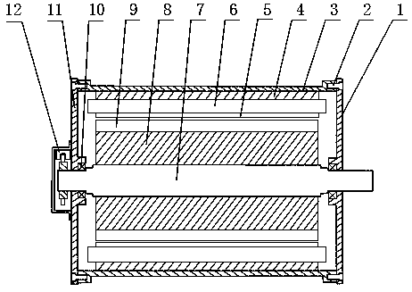
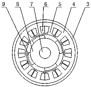
[0022] The stator 4 of the present invention is made by stacking silicon steel sheets, the rotor 8 is made of manganese steel or other non-magnetic materials, and the permanent magnet poles 9 are made of permanent magnet materials such as neodymium iron boron and ferrite, and are assembled in the following manner: The concentrated winding 6 is inserted into the wire slot of the stator tooth pole 5 in turn according to the three phases of A, B and C, and the wiring is drawn out, and the insulation treatment is carried out. The polarities of NS and SN are arranged alternately, the main shaft 7 is fixed to the rotor 8, the rear end of the main shaft 7 is used as an output shaft, and the stator 4 is fixed in the casing 3, supported by the front cover 1, the rear cover 11 and the bearing 10, The rotor 8 is suspended between the stators 4, and then the front cover 1, the rear cover 11 and the casing 3 are bolted by bolts 2, the detection disk 17 is fixed on the outside of the rear co...


PUM


Abstract

A three-pole effect permanent magnet direct current motor belongs to the field of energy-saving motor development. The motor is mainly composed of a casing, front and rear end covers, a stator, a concentrated winding, a rotor, permanent magnet poles, a position signal detection system, an electronic driving system and the like, wherein a three-phase concentrated winding is arranged on the stator;three-to-three conduction is carried out according to a triangular connection method; the permanent magnet poles are tangentially magnetized and then adhered to the surface of the rotor; the magneticflux direction is tangential; magnetic flux directions of adjacent magnetic poles are opposite; ratio of the number of the permanent magnet poles to the number of the stator tooth poles is 1: 1. 3, the width of the rotor permanent magnet pole is 1.5 times of the width of the stator tooth pole; the stator windings are reversed by 90 degrees in advance, so that the permanent magnet poles are locatedin the middles of the reversing windings, the reversing windings are reversed outside the rotor permanent magnet poles, effective cutting of the reversing windings to magnetic lines of force is reduced, counter electromotive force is greatly reduced, the energy-saving effect is remarkable, permanent magnet energy can be deeply developed and utilized, the structure is simple, and manufacturing iseasy.

Description

technical field [0001] The invention belongs to the field of energy-saving motor development, in particular to a three-pole effect permanent magnet DC motor of a DC brushless motor. Background technique [0002] With the development of the economy and the continuous growth of energy demand, energy conservation and environmental protection have become the top priority of all mankind. In recent years, my country's industrial economy has developed rapidly, and electricity demand has continued to increase. At present, industrial electricity consumption accounts for more than 70% of the total electricity consumption of the whole society. %, the contradiction between the limited power resources and the rapid development of the industry and the environmental constraints are gradually emerging, and the motor energy consumption accounts for about 65% of the industrial electricity consumption. Textiles, CNC machine tools, construction machinery, elevators, wind power generation and mili...

Claims


Application Information

Patent Timeline
Patent Type & Authority Applications(China)
IPC IPC(8): H02K29/06H02K3/28H02K1/27
CPCH02K1/278H02K3/28H02K29/06H02K2213/03
Inventor 安明武
Owner 安明武
Learn More