
Electric propulsion system

a technology of electric propulsion and propulsor, which is applied in the direction of generator/motor, electric apparatus, dynamo-electric machines, etc., can solve the problems of large industrial implementation difficulties, limited fuel capacity, and devices that are not ecologically clean, and achieves the effect of facilitating considerable increase of operating radius, specific power and efficiency factor, and high efficiency factor of the propulsor

Inactive Publication Date: 2020-05-28
LIMANSKIY VALENTIN GRIGORYEVICH
View PDF0 Cites 0 Cited by
  • Summary
  • Abstract
  • Description
  • Claims
  • Application Information

AI Technical Summary

Benefits of technology

The invention is a new electric device that generates thrust. It is designed to be highly efficient, eco-friendly, and can be used in various applications. The device works by using electricity to create movement in capacitors, which results in thrust. The efficiency factor of the device is higher than traditional motors and jet engines. The device does not require any fuel and is typically clean. The technical effects of the invention include increased power, specific power, and operating radius of the electric propulsor. Overall, the invention allows for the creation of a more advanced, eco-friendly electric thrust generator.

Problems solved by technology

Such devices are not ecologically clean.
Their radius of operation is limited by fuel capacity which is especially true in the case of jet engines.
There are also ideas related to ion jet engines, including those based on Brown effect, but their industrial implementation meets great difficulties.
At present there is a great number of erroneous literature, including patent-literature, devoted to “propulsors” based on electric and / or magnetic interaction of closed electric currents (erroneous literature is not accepted to refer to as it produces no result).
This explains the lack of appropriate technical results—commercially available electric propulsion devices.
Thrust can arise in some systems with non-closed electric currents.

Method used


Image

  • Electric propulsion system

Examples


example 1

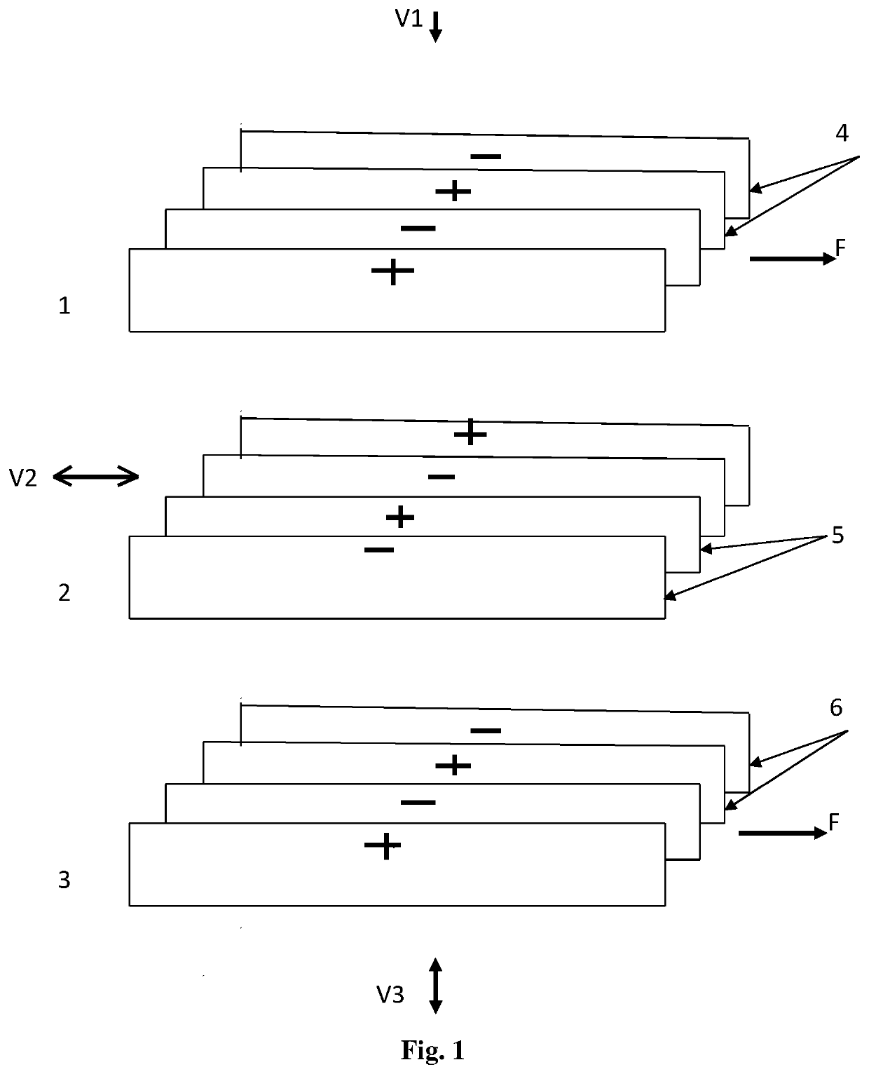
[0023]The drawing shows end view of electro-magnetic system of electric propulsor comprising three devices 1, 2 and 3 (according to the second invention variant), aligned in a row: each containing, on top, in the center and below, two or more, aligned parallel, conductive, properly insulated, strong flat plates 4 (5, 6) forming, on the whole, electric capacitor 1 (2, 3). Flat plates 4, 5 and 6 of all electric capacitors are parallel to one plane—vertical in this case. Electric capacitors 1, 2 and 3 are adapted to reciprocal movement of charged flat plates, each in its plane. Wherein, if all flat plates 4 (5, 6) in the said electric capacitor 1 (2, 3) are moving, movement velocities V1 (V2, V3) of its oppositely charged plates differ in sign (direction); plates 4 of electric capacitor 1, located on top, are moving reciprocally and vertically: up- and down. Movement velocities of flat plates 4 and 6 of two electric capacitors 1 and 3, located below and on top, differ in sign while pla...

example 2

[0029]Another variant of electric propulsor without lower or upper electric capacitors can be devised if necessary. In such case, the electric propulsor comprises two electric capacitors, for example, only 1 and 2 (see the drawing disregarding electric capacitor 3). Flat plates 4 and 5 of electric capacitors 1 and 2 are located as in example 1, and electric capacitors 1 and 2 are adapted to the corresponding movement of flat plates 4 and 5, see description of plates in Example 1.

[0030]According to the second variant, the electric propulsor operates similarly to the first variant of electric propulsor. Wherein Lorentz forces which arise in moving flat plates 4 and 5 of these two electric capacitors 1 and 2 can also be easily determined with the use of left-hand rule (see reference [1], page 102).

[0031]The described electric propulsor can have more than three electric capacitors, aligned in a row (not shown in the drawing). At that, the electric capacitors, located next but one, are a...


PUM


Abstract

The proposed electric propulsion system is designed for generating thrust, improving environmental performance. An embodiment of the system includes three devices, each containing two or more insulated current-conducting plates arranged in parallel and forming an electric capacitor. The capacitors are arranged in a row such that the second electric capacitor is disposed between the first capacitor and the third capacitor. Each capacitor is designed such that at least one charged plate is capable of reciprocating motion. When identically charged plates are moving, their velocities have the same sign. The plates of the first and third capacitors move in a direction toward and away from the second capacitor, and the plates of the second capacitor move in a direction transverse to the direction of movement of the plates of the first and third capacitors. The sign of the velocities of all of the plates changes at the same time.

Description

CROSS-REFERENCE TO RELATED APPLICATIONS[0001]This application is a U.S. national stage application of an international application PCT / RU2017 / 000833 filed on 8 Nov. 2017, whose disclosure is incorporated herein in its entirety by reference, which international application claims priority of a Russian Federation patent application RU2017119201 filed on 1 Jun. 2017.FIELD OF THE INVENTION[0002]This invention relates to the field of electric propulsion engineering and can be used to create thrust which in turn can be used in various devices. An electric propulsor device (herein also called ‘electric propulsion device’ or ‘electric propulsor’) does not need any fuel and combustion chamber for its operation, is ecologically clean and has the potential of application in transportation for propulsion of ground and space vehicles, in power engineering, mechanical engineering, construction industry, space exploration and other technical fields.BACKGROUND OF THE INVENTION[0003]Currently the pr...

Claims


Application Information

Patent Timeline
Patent Type & Authority Applications(United States)
IPC IPC(8): H02N11/00H02K53/00
CPCH02N11/008H02K53/00H02N11/006
Inventor LIMANSKIY, VALENTIN GRIGORYEVICH
Owner LIMANSKIY VALENTIN GRIGORYEVICH
Learn More