Heat-pipe type flat plate collector

A flat plate collector and heat pipe technology, which is applied to solar collectors, components of solar collectors, solar collectors using working fluid, etc. The problem of large resistance, etc., can overcome the large contact thermal resistance, improve the effective utilization rate, and improve the efficiency factor.

Pending Publication Date: 2018-09-28
INST OF ENGINEERING THERMOPHYSICS - CHINESE ACAD OF SCI +1
View PDF0 Cites 0 Cited by
  • Summary
  • Abstract
  • Description
  • Claims
  • Application Information

AI Technical Summary

Problems solved by technology

[0008] The object of the present invention is to solve the above technical problems. The heat pipe type flat plate heat collector provided by the present invention has a reasonable structure and uses the phase change heat transfer principle of evaporation and condensation to transfer heat to the cooling medium in a "nearly zero thermal resistance" manner. Among them, the problem of large flow resistance and uneven flow distribution of the flat plate heat collection system is solved, the efficiency factor of the heat collector is improved, and the effective utilization rate of energy is improved

Method used


Image

  • Heat-pipe type flat plate collector
  • Heat-pipe type flat plate collector

Examples


Embodiment Construction

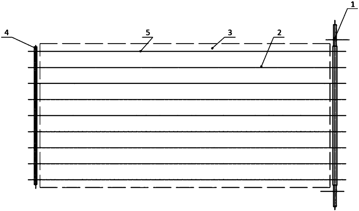
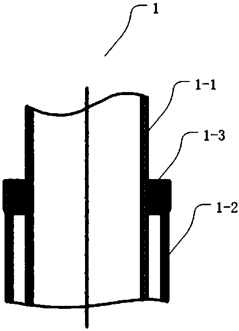
[0024] Figure 1 to Figure 2 It is a heat pipe type flat plate heat collector according to the present invention, and the present application will be described in detail below in conjunction with specific embodiments and accompanying drawings.

[0025] The examples described here are specific specific implementations of the present invention, and are used to illustrate the concept of the present invention. They are all explanatory and exemplary, and should not be construed as limiting the implementation of the present invention and the scope of the present invention. In addition to the embodiments described here, those skilled in the art can also adopt other obvious technical solutions based on the claims of the application and the contents disclosed in the description, and these technical solutions include adopting any obvious changes made to the embodiments described here. Replacement and modified technical solutions.

[0026] The accompanying drawings in this specification...


PUM


Abstract

The invention discloses a heat-pipe type flat plate collector. The heat-pipe type flat plate collector comprises an external frame, a heat absorption plate core and light-transmitting glass. The heatabsorption plate core is arranged inside the external frame, and the light-transmitting glass is arranged on the upper portion of the external frame. The heat absorption plate core is an overall-heat-pipe type heat absorption plate core and is composed of a cold fluid passage pipe, heat transfer pipes, a heat absorption film, flow collecting pipes and a flow return pipe. The cold fluid passage pipe comprises an inner pipe body, an outer pipe body and a blocking plate, and the blocking plate is welded between the inner pipe body and the outer pipe body. The heat transfer pipes, the heat absorption film, the flow collecting pipes, the flow return pipe and the outer pipe body are made of aluminum. The heat transfer pipes and the flow return pipes are welded between the outer pipe body and theflow collecting pipe in parallel to form a pipe assembly, and the heat absorption film is welded to the pipe assembly. A cooling medium is transmitted to the upper end of the inner pipe body from thelower end, and the pipe assembly is filled with a phase change medium. The heat-pipe type flat plate collector provided by the invention is reasonable in structure, the problems that a flat plate heat collection system is large in flowing resistance and uneven in flow distribution are solved, the efficiency factor of the collector is improved, and the effective utilization rate of energy is increased.

Description

technical field [0001] The invention relates to a tube type heat collector, in particular to a heat pipe type flat plate heat collector. Background technique [0002] Flat plate collectors are widely used due to their high heat collection efficiency and large effective energy utilization. However, copper tubes are used as heat-absorbing materials in flat plate collectors, which are heavy and expensive, and have been difficult to be widely used. [0003] The core component of the flat-plate collector is composed of a black-painted heat-absorbing plate, with copper tubes as fluid channels, and is composed of laser welding, diffusion welding and other methods. The laser welding method between the heat absorbing plate and the fluid channel tube will deviate from the theoretical assumptions to a large extent, and there is an air gap between the welds, which increases the contact thermal resistance formed by the point contact in the structure, thereby reducing the concentration. ...

Claims


Application Information

Patent Timeline
Patent Type & Authority Applications(China)
IPC IPC(8): F24S10/95F24S70/12F24S80/30
CPCY02E10/44
Inventor 袁达忠
Owner INST OF ENGINEERING THERMOPHYSICS - CHINESE ACAD OF SCI
Why Eureka
Try Eureka