Screw rod supporting device on planer type milling machine with moving workbench

A technology of gantry milling machine and support device, which is applied in the direction of manufacturing tools, metal processing equipment, metal processing machinery parts, etc., which can solve problems such as screw deflection deformation, reduce machine tool stability, and feed axis movement accuracy error, etc., to reduce positioning Accuracy error and its impact on workpiece processing accuracy, increase stability and safety, and eliminate bending and deflection deformation

Inactive Publication Date: 2012-08-15
SUZHOU JIANG YUAN PRECISION MACHINERY
View PDF7 Cites 7 Cited by
  • Summary
  • Abstract
  • Description
  • Claims
  • Application Information

AI Technical Summary

Problems solved by technology

When the stroke of the workbench moving back and forth is large, the length of the screw is required to be very long, and the suspended part in the middle of the screw will cause deflection and deformation of the screw due to its own weight, causing the middle part of the ball screw to bend downward, which will affect The stability of the movement of the worktable reduces the smooth operation of the machine tool and causes errors in the movement accuracy of the feed axis, resulting in errors in the machining accuracy of the workpiece

Method used


Image

  • Screw rod supporting device on planer type milling machine with moving workbench
  • Screw rod supporting device on planer type milling machine with moving workbench
  • Screw rod supporting device on planer type milling machine with moving workbench

Examples


Embodiment Construction

[0011] The structure of the present invention will be further described below in conjunction with the accompanying drawings.

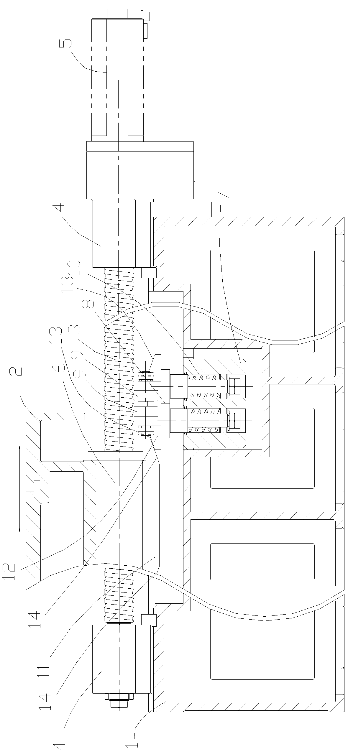
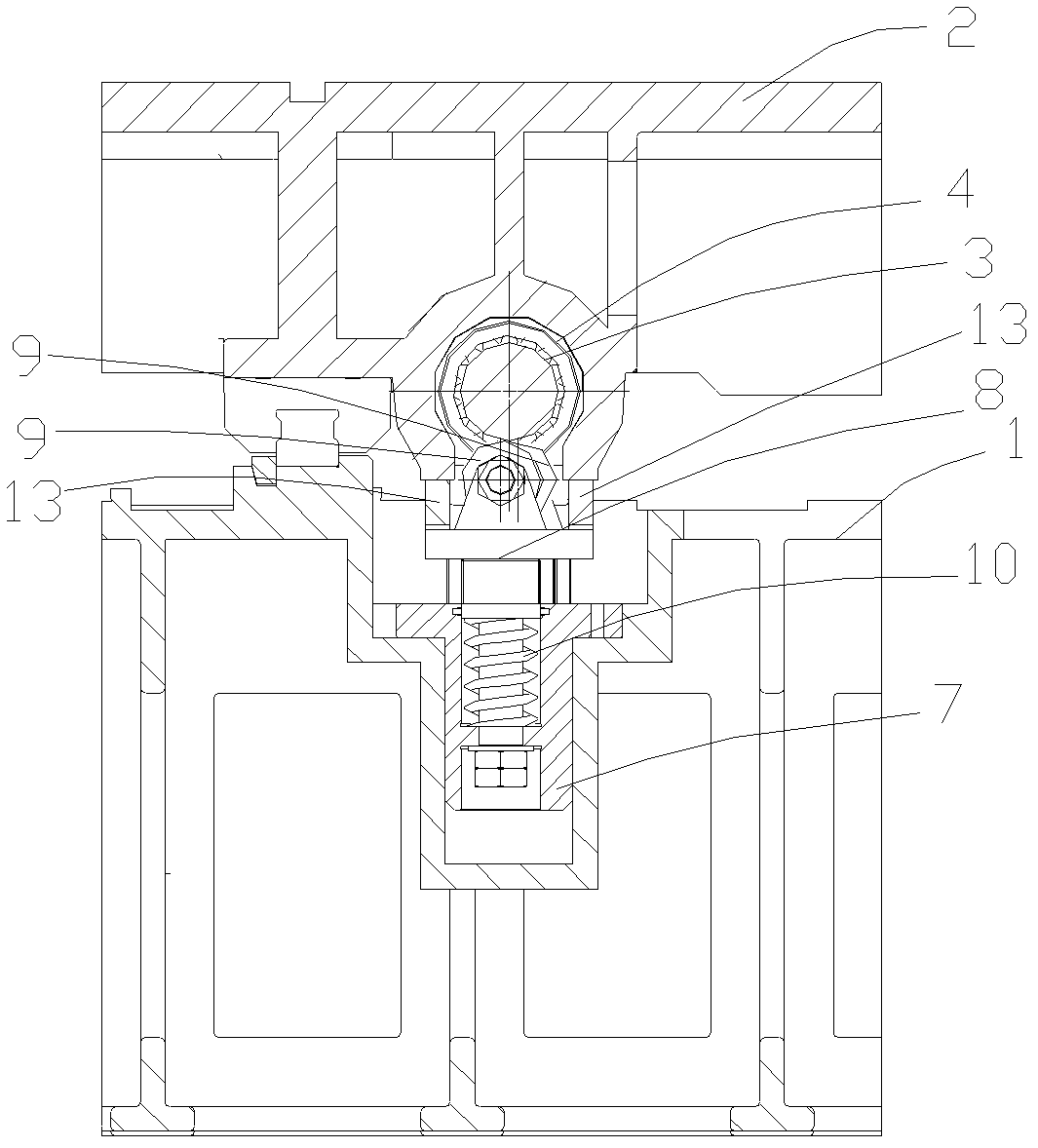
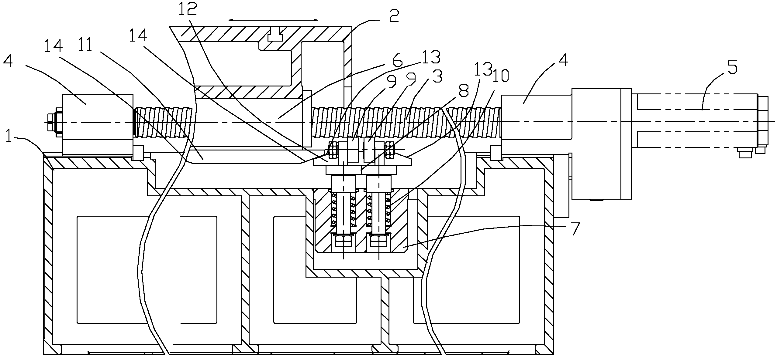
[0012] see Figure 1-2 As shown, on the workbench mobile gantry milling machine, the screw support device includes a bed 1, a workbench 2, a screw 3, a nut 6, a motor 5, a mounting seat 7, a support 8, a pair of rollers 9, an elastic member 10. Both ends of the lead screw 3 are provided with bearings, and the bearings at both ends of the lead screw 3 are set on the bed 1 through the bearing housing 4, the lead screw 3 can rotate, and the rotating lead screw 3 is driven by the motor 5, The thread on the lead screw 3 is matched with a nut 6, the nut 6 is fixed with the workbench 2, the lead screw 3 rotates, the nut 6 moves back and forth along the length direction of the lead screw 3, then the workbench 2 moves forward and backward, and the lead screw 3 moves back and forth. The length direction extends horizontally, such as figure 1 , a mounting...


PUM


Abstract

The invention discloses a screw rod supporting device on a planer type milling machine with a moving workbench. The screw rod supporting device comprises a mounting seat, a supporting piece, at least one pair of rollers and an elastic piece, wherein the mounting seat is fixed on a machine tool body; the supporting piece is arranged on the mounting seat in a manner of moving up and down; the rollers are arranged on the supporting piece, and the axle axes of the rollers can extend along the length direction of a screw rod; the elastic piece is arranged between the supporting piece and the mounting seat and can supply an upward elastic resetting force to the supporting piece, so that the circumferences of the rollers can be upwards pressed against the screw rod; the rollers are positioned in the middle of the screw rod or under a position close to the middle of the screw rod; the paired rollers are arranged longitudinally at an interval along the length direction of the screw rod; and the paired rollers are symmetrically arranged transversely according to an upright central line of the screw rod on an upright projection surface of the screw rod. Due to the elastic piece, the rollers elastically support the middle or the position close to the middle of the screw rod, so that bending and flexible deformation of the screw rod are reduced or eliminated; and furthermore, the positioning precision error of the motion of the workbench and the influence on the machining precision of a workpiece are reduced, the positioning precision of a machining shaft of a machine tool is improved, and the stability and the safety of running are improved.

Description

[0001] technical field [0002] The invention relates to a lead screw supporting device on a movable workbench type gantry milling machine. Background technique [0003] In the table mobile gantry milling machine, the drive mode of the table is divided into two types: ball screw drive and rack and pinion drive. In the ball screw drive mode, both ends of the ball screw are set with bearings, and are supported by the bearing seat. The servo motor drives the screw to rotate, and the nut threaded on the screw will move back and forth. The worktable and the nut If it is relatively fixed, the workbench can move back and forth. When the stroke of the workbench moving back and forth is large, the length of the screw is required to be very long, and the suspended part in the middle of the screw will cause deflection and deformation of the screw due to its own weight, causing the middle part of the ball screw to bend downward, which will affect The stability of the table movement re...

Claims


Application Information

Patent Timeline
Patent Type & Authority Applications(China)
IPC IPC(8): B23Q1/46
Inventor 吉文正杨威
Owner SUZHOU JIANG YUAN PRECISION MACHINERY
Why Eureka
Try Eureka