Center-aligning floating clamping fixture

A floating clamping and fixture technology, applied in the direction of clamping, manufacturing tools, supports, etc., can solve problems such as inconsistent processing dimensions, large coaxiality errors, and affecting radial runout of finished components.

Inactive Publication Date: 2012-08-15
SHENZHEN CEMCN
View PDF10 Cites 48 Cited by
  • Summary
  • Abstract
  • Description
  • Claims
  • Application Information

AI Technical Summary

Problems solved by technology

The disadvantages are: the steel pipe itself has a certain ellipticity, and it is clamped by self-centering or conical surface fixtures. The steel pipe is deformed after clamping and positioning, and the two ends of the steel pipe are round during processing. The processing size of the steel pipe to be processed is inconsistent before and after clamping, resulting in a large coaxiality error between the inner hole processing cylindrical surface and the outer diameter cylindrical surface at both ends of the steel pipe, which seriously affects the finished component. Roller" Radial Jump Over Index

Method used


Image

  • Center-aligning floating clamping fixture
  • Center-aligning floating clamping fixture

Examples


Embodiment Construction

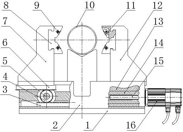
[0007] The present invention will be described in further detail below in conjunction with the accompanying drawings.

[0008] like figure 1 As shown, the self-aligning floating clamping fixture includes a fixture support frame 1, and the fixture support frame 1 is connected to the mounting plate 2. A gear shaft 5 is also arranged on the support frame 1, and a gear shaft 5 is fixed on the gear shaft 5. Gear 4, said gear 4 meshes with rack one 3 positioned below the fixture and rack two 6 positioned above the fixture respectively, said rack one 3 is connected to a transmission slider 14, said transmission slider 14 is connected to a transmission screw 15, the transmission screw is connected with the motor 16, the motor 16 is fixed on the fixture support frame 2, the rack 2 6 is connected with the left chuck column 7, and the left chuck column 7 is provided with a V-shaped The jaws 8, the V-shaped jaws 8 are connected to the pin shaft 9, the pin shaft 9 is connected to the clam...


PUM


Abstract

The invention discloses a center-aligning floating clamping fixture used in a machine tool for two ends of a steel pipe. The structure of the center-aligning floating clamping fixture comprises a fixture supporting frame, a driving mechanism, a transmission mechanism, a clamping mechanism and a floating aligning mechanism, wherein the transmission mechanism and the clamping mechanism are connected with each other, the clamping mechanism is provided with two chuck uprights which are parallel to each other in opposite directions, the uprights are provided with V-shaped jaws and connected with a bracket, a V-shaped clamp is provided with two pairs of floating clamping blocks, clamping surfaces of the clamping blocks are multidentate clamping surfaces, and the multidentate clamping surfaces are positioned on a same cylindrical surface. The center-aligning floating clamping fixture can be used for special machine tool equipment for machining the two ends of the steel pipe of a DT II type roller of a belt conveyor, and the geometric axis center of the steel pipe to be automatically aligned with the axis center of the machine tool so as to control radial deformation of the steel pipe.

Description

technical field [0001] The invention relates to a fixture for a steel pipe processing machine tool, in particular to a fixture for special machine tool equipment for double-end processing of a "belt conveyor DTII idler" steel pipe. Background technique [0002] In the existing equipment for processing the inner holes at both ends of the idler steel pipe, the fixtures mostly adopt a self-centering fixture structure, or a tapered surface fixture structure for positioning, and carry out boring or turning processing. The disadvantages are: the steel pipe itself has a certain ellipticity, and it is clamped by self-centering or conical surface fixtures. The steel pipe is deformed after clamping and positioning, and the two ends of the steel pipe are round during processing. The processing size of the steel pipe to be processed is inconsistent before and after clamping, resulting in a large coaxiality error between the inner hole processing cylindrical surface and the outer diamete...

Claims


Application Information

Patent Timeline
Patent Type & Authority Applications(China)
IPC IPC(8): B23Q3/00
Inventor 不公告发明人
Owner SHENZHEN CEMCN
Why Eureka
Try Eureka