Automatic packer of steel pipe

A technology of automatic packaging and steel pipes, which is applied to the parts of packaging and binding machinery, can solve the problems of high labor intensity, waste of packing belt materials, and low strength, and achieve scientific and reasonable structural design, overcome time-consuming and labor-intensive, high degree of automation Effect

Inactive Publication Date: 2012-08-15
天津市友发德众钢管有限公司
View PDF8 Cites 19 Cited by
  • Summary
  • Abstract
  • Description
  • Claims
  • Application Information

AI Technical Summary

Problems solved by technology

At present, the packing of steel pipes cannot be mechanized, and the steel pipes are mainly stacked on the packing support manually, and then bundled, and the two ends of the packing belt are welded and fixed.
There are many disadvantages in the existing steel pipe packaging method: the most prominent is that the packaging bracket has a simple structure and only plays a supporting role. It requires multiple processes such as manual palletizing, manual bundling, and manual welding. It requires the cooperation of multiple people to complete, and the efficiency is low. Moreover, the labor intensity is very high, and the operator cannot work for a long time in the packing position; secondly, the manual binding strength of the packing belt is small during the packing process, which is prone to loose bags, which affects the lifting and transportation in the later stage; thirdly, when packing manually, the packing belt A long section needs to be reserved at the butt joint to facilitate welding after the butt joint. The end of the strap after welding is not compliant, which affects the appearance of the steel pipe bag and wastes the material of the strap; in addition, when the steel pipe is packed, it is usually necessary The packing belt is put on the backing tube. When packing manually, the fitting and adjustment of the backing tube is time-consuming and laborious.

Method used


Image

  • Automatic packer of steel pipe
  • Automatic packer of steel pipe
  • Automatic packer of steel pipe

Examples


Embodiment Construction

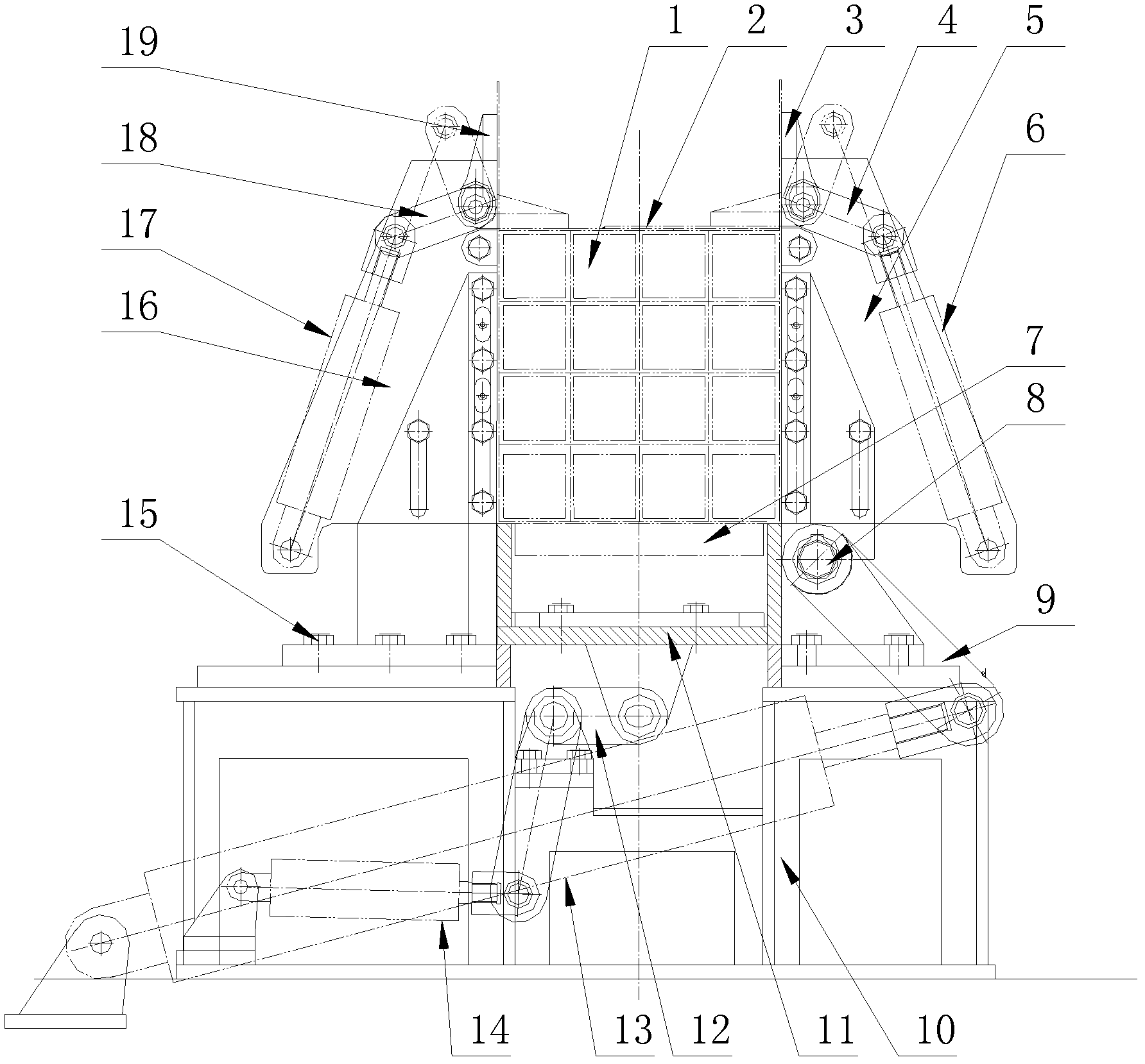
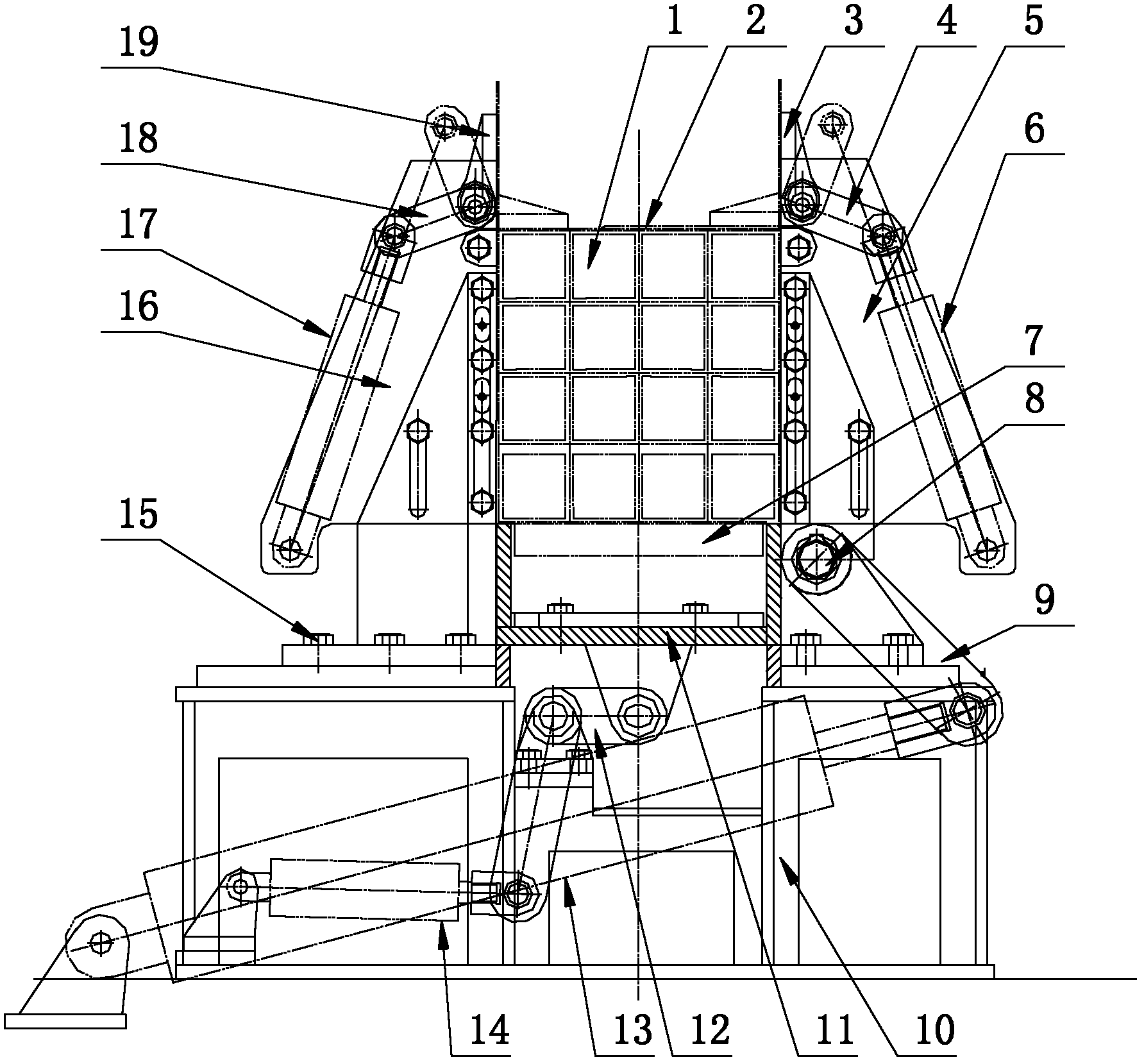
[0025] The present invention will be further described in detail below through specific embodiments in conjunction with the accompanying drawings. The following examples are only descriptive, not restrictive, and cannot limit the protection scope of the present invention.

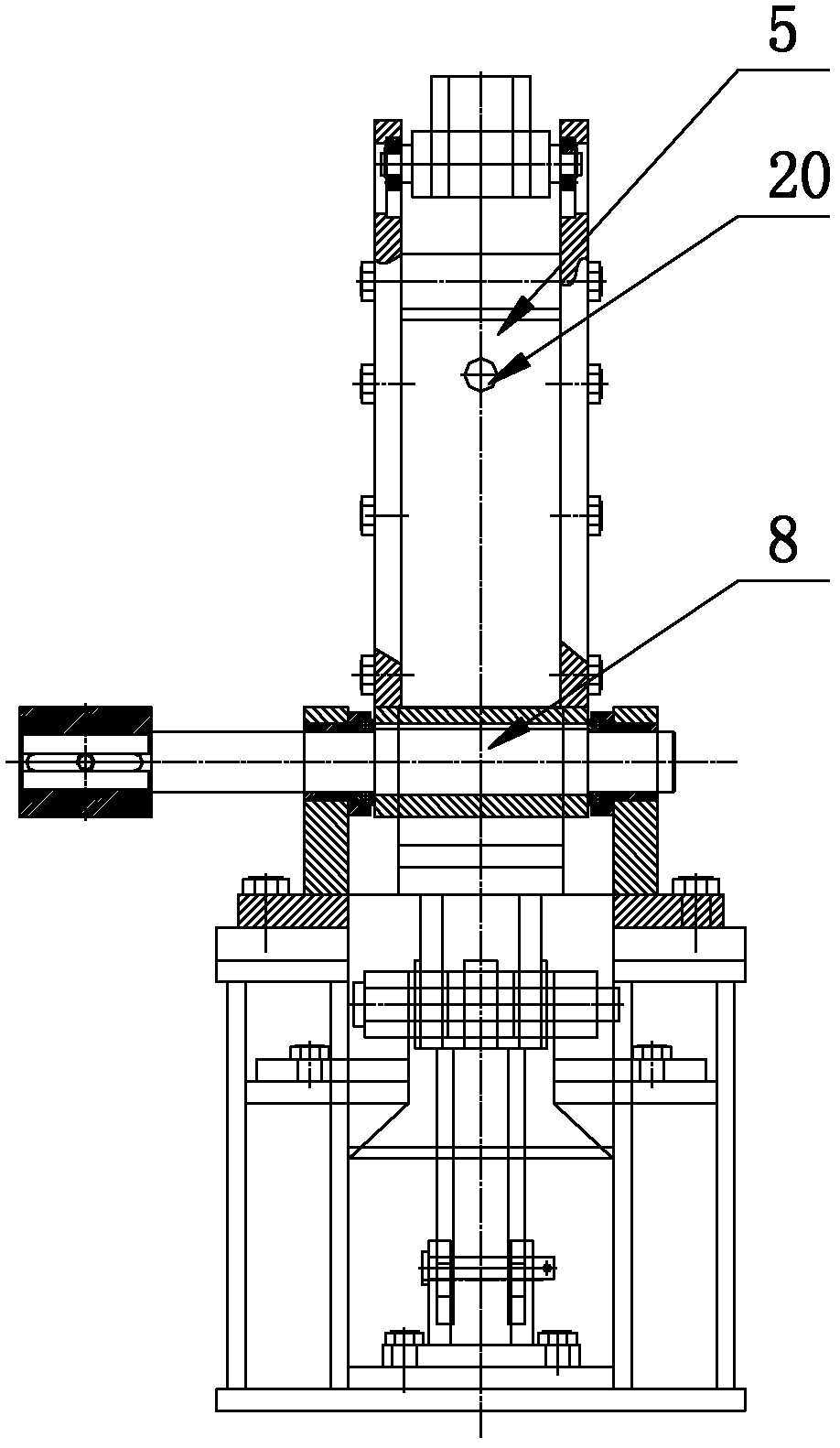
[0026] An automatic packaging device for steel pipes, comprising a machine base 10, a steel pipe bracket 11, a fixed arm 16, an overturning arm 5, and an overturning drive mechanism, a steel pipe bracket is installed in the middle of the machine base, and a vertical The fixed arm is directly installed, and the lower part of the fixed arm is installed on the machine base through bolts 15, which can move horizontally to meet the different width requirements of steel pipe bundles. Install the turning arm on the machine base on the other side of the steel pipe bracket. The lower end of the turning arm is rotated and installed on the machine base through the swing shaft 8. The swing shaft of the turning arm is d...


PUM


Abstract

The invention relates to an automatic packer of a steel pipe, comprising a machine seat, a steel pipe support, a fixing arm, an overturning arm and an overturning driving mechanism, wherein the steel pipe support is arranged at the middle part of the machine seat, the fixing arm is vertically arranged on the machine seat on one side of the steel pipe support, the overturning arm is arranged on the machine seat on the other side of the steel pipe support, the lower end of the overturning arm is rotatably arranged on the machine seat through a swinging shaft, the swinging shaft of the overturning arm is driven by the overturning driving mechanism at the lower part of the machine seat, and a pressing mechanism is arranged on the fixing arm and is also arranged on the overturning arm. The automatic packer disclosed by the invention is designed scientifically and reasonably, overcomes the defects of wasting time and labor in a traditional manual binding manner, has the advantages of high automatic degree and efficiency, low labor strength, low possibility of baling off and attractive appearance, completely liberates an operator from a complex operation of packing the steel pipes and also has higher innovativeness.

Description

technical field [0001] The invention relates to a steel pipe packing device, in particular to a steel pipe automatic packing device. Background technique [0002] The last process of steel pipe processing is packing. After packing, the steel pipes are easier to lift and transport. At present, the packing of steel pipes cannot be mechanized. It mainly relies on manual stacking of steel pipes on the packing support, then bundling, and welding and fixing the two ends of the packing belt. There are many disadvantages in the existing steel pipe packaging method: the most prominent is that the packaging bracket has a simple structure and only plays a supporting role. It requires multiple processes such as manual palletizing, manual bundling, and manual welding. It requires the cooperation of multiple people to complete, and the efficiency is low. Moreover, the labor intensity is very high, and the operator cannot work for a long time in the packing position; secondly, the manual ...

Claims


Application Information

Patent Timeline
Patent Type & Authority Applications(China)
IPC IPC(8): B65B27/10B65B13/18
Inventor 陈自林刘凯元高建国孙立辛世龙张金国
Owner 天津市友发德众钢管有限公司
Why Eureka
Try Eureka