
Adjustable sizing block

A pad iron and washer technology, applied to the frame of the engine, supporting machines, mechanical equipment, etc., can solve the problems of heavy workload, increased production cost, waste of materials and stacking space, etc., and achieve the effect of easy operation and cleanliness

Inactive Publication Date: 2012-08-15
CHINA UNITED ENG
View PDF9 Cites 40 Cited by
  • Summary
  • Abstract
  • Description
  • Claims
  • Application Information

AI Technical Summary

Problems solved by technology

The height of the commonly used shim irons is constant, one shim iron can only be used for a single height adjustment, and shim irons of different specifications are used for different height adjustments
However, due to the diversity of the tested products and the errors in the processing of the tested products, it is necessary to replace the pad irons of different specifications when installing different tested products. As a result, many specifications need to be prepared. It wastes materials and stacking space, increases equipment investment, increases production costs, also brings inconvenience to use, increases workload, and reduces installation efficiency
[0003] There are also some height-adjustable shims now, as disclosed on July 23, 2008, in a Chinese patent with a publication number of CN201090908, which discloses a kind of adjustment shim, which adjusts the force of the slide block in the shim It is mainly due to the unilateral shear force of the wedge on it. If the weight of the tested product on the pad iron is heavy, it is difficult to adjust the pull slider, and the unilateral shear force is easy to scratch the thread, so the adjustment The shim is not suitable for the heavy-duty environment that needs to be adjusted frequently. In addition, the adjustable shim only has the function of adjustment and has no fixed function
Another example is that the publication date is November 15, 2006, and the publication number is CN2837986 in the Chinese patent, which discloses an adjustable shim, and the joint surface of the lifting wedge and the slider in the adjustable shim is completely exposed to the outside world. , For the factory environment, there are often sundries falling on the wedging surface, which will cause wear on the wedging surface over time, and its inclination angle is greater than the self-locking angle, because its own friction cannot overcome the upper Therefore, the horizontal thrust of the wedge on the block and the thrust of the adjusting bolt are very large, which is dangerous. In addition, the adjustable shim only has the function of adjustment and has no fixing function.
It can be seen that the above two shims are not suitable for working under heavy loads and environments requiring frequent adjustments
[0004] In addition, the publication date is October 20, 2010, and the publication number is CN101862969A in the Chinese patent, which discloses an adjustable pad iron, which includes a steel wire retaining ring, a locking block, a locking screw, a base, Wrench hole, nut sleeve and top block on the groove surface, the steel wire retaining ring is set in the top block on the groove surface, the nut sleeve is set on the base, four wrench holes are evenly distributed along the circumferential direction of the nut sleeve, and the nut needs to be rotated with a matching wrench When the nut sleeve is rotated to the ideal position, the other end of the supporting wrench is used to turn the locking screw so that the locking block is pressed against the threaded part of the sleeve. The structure is complex, it is inconvenient to use, the workload of adjustment is large, and the adjustment accuracy is poor
[0005] To sum up, there is currently no adjustable shim iron with simple structure, reasonable design, easy operation, high adjustment accuracy, and suitable for heavy loads and environments requiring frequent adjustments.

Method used


Image

  • Adjustable sizing block
  • Adjustable sizing block
  • Adjustable sizing block

Examples


Embodiment Construction

[0017] The present invention will be further described in detail below in conjunction with the accompanying drawings and through the examples. The following examples are to explain the present invention and the present invention is not limited to the following examples.

[0018] Example.

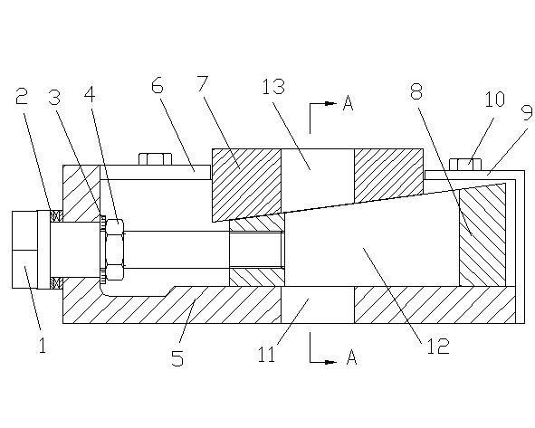
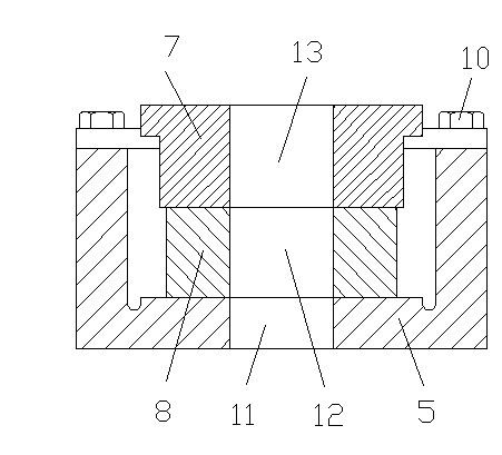
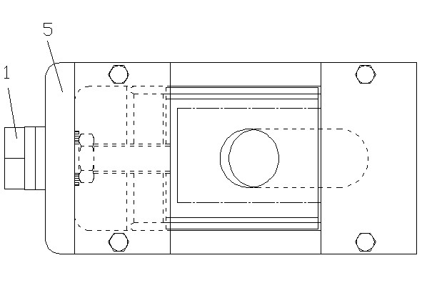
[0019] see Figure 1 to Figure 3 , The adjustable pad iron in this embodiment includes an adjusting screw 1 , a thrust bearing 2 , a washer 3 , a tightening nut 4 , a base 5 , a lifting wedge 7 and a sliding block 8 .

[0020] The base 5 in this embodiment includes a bottom plate, two side plates, an adjusting screw support plate, a baffle 6 and a stopper 9, wherein the two side plates are respectively fixed on both sides of the bottom plate, and the adjusting screw supporting plate is fixed on the bottom plate , the two sides of the adjusting screw support plate are respectively fixed with the two side plates. The stopper 9 in this embodiment is a structure in which the "L" character is r...


PUM


Abstract

The invention relates to an adjustable sizing block. At present, an adjustable sizing block capable of being used in overloading environments and environments requiring frequent adjustments is not provided. The adjustable sizing block is characterized by comprising a base, a slide block, an adjusting screw rod, a fastening nut and a lifting wedge block, wherein a slide block sliding cavity, an adjusting screw rod hole, a base through hole and a horizontal limiting port are formed in the base; the top surface of the slide block is an upper inclined plane of the slide block, and a slide block through hole and an adjusting screw hole are formed on the top surface of the slide block; the slide block is positioned in the slide block sliding cavity; the slide block through hole is positioned right above the base through hole; the adjusting screw rod is penetrated into the adjusting screw rod hole, and is connected with the adjusting screw hole through threads; the fastening nut is connected to the adjusting screw rod through threads; the bottom surface of the lifting wedge block is a lower inclined plane of the wedge block, the top surface of the lifting wedge block is an upper plane of the wedge block, and a wedge block through hole is formed on the top surface of the lifting wedge block; the lifting wedge block is arranged on the slide block; the wedge block through hole is positioned right above the slide block through hole; and the lifting wedge block is positioned in the horizontal limiting port. The adjustable sizing block is easy to operate, and is applicable in the overloading environments and the environments requiring frequent adjustments.

Description

technical field [0001] The present invention relates to a pad iron, in particular to an adjustable pad iron, which is mainly suitable for heavy loads and places that need to be adjusted frequently. Background technique [0002] At present, on many product test benches, when installing the tested product, it is often necessary to use a bolster to adjust the installation height of the tested product. The height of the commonly used horns is constant, a horn can only be used for a single height adjustment, and the horns of different specifications are used for different height adjustments. However, due to the diversity of the tested products and the errors in the processing of the tested products, it will lead to the need to replace the pads of different specifications when installing different tested products. As a result, many specifications need to be prepared. It wastes materials and stacking space, increases equipment investment, increases production costs, brings inconve...

Claims


Application Information

Patent Timeline
IPC IPC(8): F16M7/00
Inventor 张明锋陈波吴浩亮方正匡中付曾鹏
Owner CHINA UNITED ENG
Features
  • Generate Ideas
  • Intellectual Property
  • Life Sciences
  • Materials
  • Tech Scout
  • Unparalleled Data Quality
  • Higher Quality Content
  • 60% Fewer Hallucinations
Learn More