Polarity tester of current transformer

A technology of current transformer and tester, applied in the direction of instruments, measuring electricity, measuring devices, etc., can solve the problems of time-consuming, laborious, low automation process, etc., to ensure the safety of the power grid, improve the reliability of power supply, and facilitate the polarity test. Effect

Inactive Publication Date: 2012-08-15
XUZHOU POWER SUPPLY OF JIANGSU ELECTRIC POWER +1
View PDF2 Cites 3 Cited by
  • Summary
  • Abstract
  • Description
  • Claims
  • Application Information

AI Technical Summary

Problems solved by technology

However, most of the current transformer polarity test, transformation ratio test and other work still continue the traditional method, which has the disadvantages of low automation, time-consuming and labor-intensive.

Method used


Image

  • Polarity tester of current transformer
  • Polarity tester of current transformer
  • Polarity tester of current transformer

Examples


Embodiment Construction

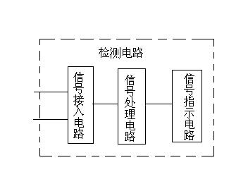
[0014] Such as figure 1 As shown, a current transformer polarity tester has a detection circuit, and the detection circuit includes a signal access circuit connected to the secondary side of the current transformer for outputting positive and negative peak voltages, connected to the signal access circuit respectively The signal processing circuit that converts the positive and negative peak voltages into +5V voltage is connected with the signal processing circuit to the signal indication circuit used to indicate the polarity of the current transformer.

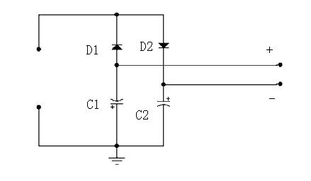
[0015] Such as figure 2 As shown, the signal access circuit includes diodes D1, D2 and electrolytic capacitors C1, C2. The cathode of diode D1 is connected to the anode of diode D1, its anode is connected to the negative pole of electrolytic capacitor C1, and the cathode of diode D2 is connected to the positive pole of electrolytic capacitor C2. The positive pole of the capacitor C1 and the negative pole of the electroly...


PUM


Abstract

The invention discloses a polarity tester of a current transformer, and relates to the technical field of polarity testing of the current transformer. The tester is provided with a shell, wherein a detection circuit is arranged in the shell and comprises a signal access circuit, a signal processing circuit and a signal indicating circuit; the signal access circuit is connected with a secondary side of the current transformer for outputting positive peak voltage and negative peak voltage; the signal processing circuit is connected with the signal access circuit for converting the positive peak voltage and the negative peak voltage into +5V voltage respectively; and the signal indicating circuit is connected with the signal processing circuit for indicating the polarity of the current transformer. The polarity tester has the advantages of time saving, labor saving, economy, practicability and capability of bringing great convenience for polarity testing of the current transformer.

Description

technical field [0001] The invention relates to the technical field of current transformer polarity testing, in particular to a current transformer polarity testing method. [0002] tester. Background technique [0003] The current transformer polarity test is a test item that must be carried out after the new current transformer or current transformer is reinstalled. It is for those protections that have strict requirements on the secondary current input of the current transformer (such as directional overcurrent protection, differential protection, etc.) and metering are critical. If the polarity direction of the current transformer is wrong, it will directly lead to protection malfunction or refusal to operate, and measurement data error. [0004] With the emergence of various testers, the automation of relay protection calibration work is also improving. However, most of the current transformer polarity test, transformation ratio test and other work still continue the...

Claims


Application Information

Patent Timeline
Patent Type & Authority Applications(China)
IPC IPC(8): G01R31/06
Inventor 肖学权刘宁许航朱金龙
Owner XUZHOU POWER SUPPLY OF JIANGSU ELECTRIC POWER
Why Eureka
Try Eureka