Zoom lens, camera, information device and portable information terminal device
A zoom lens and focal length technology, applied in the field of zoom lens, can solve the problem of large moving amount of focus, and achieve the effects of high speed, reduced driving energy, and light weight
- Summary
- Abstract
- Description
- Claims
- Application Information
AI Technical Summary
Problems solved by technology
Method used
Image
Examples
no. 1 approach 》
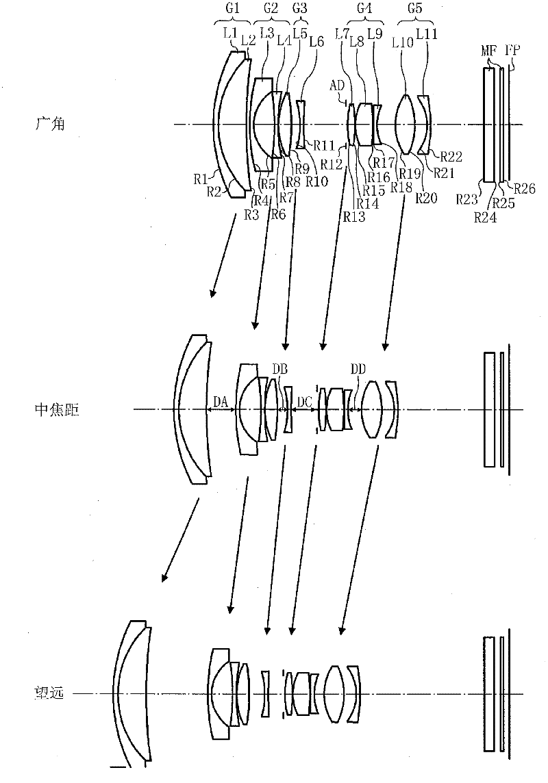
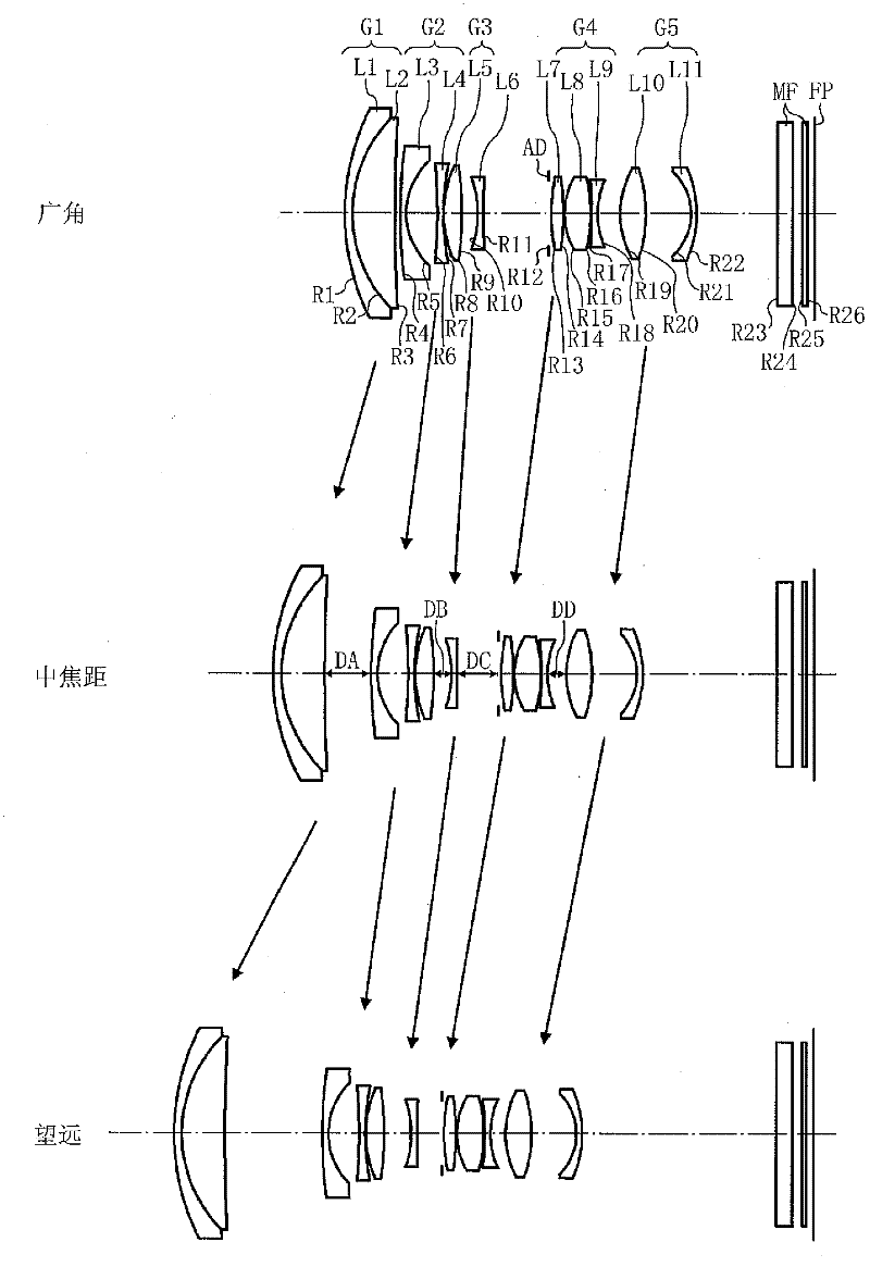
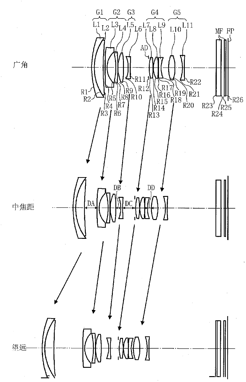
[0111] Figure 1 to Figure 5 The first embodiment of the present invention is shown.
[0112] The conditional formula (1) in the present invention represents the relationship between the focal length F2 of the second lens group and the focal length F3 of the third lens group. Since both the second lens group and the third lens group have negative refractive power, the focal lengths F2 and F3 are both negative.
[0113] If the upper limit of the conditional formula (1) is greater than -0.5, the energy of the third lens group to be calculated is relatively reduced, and the amount of movement during focusing increases, which hinders high-speed automatic focusing, or the energy of the second lens group The increase will cause the increase of the manufacturing error sensitivity, which is not conducive to the assembly performance of the lens.
[0114] On the contrary, if the lower limit value of the conditional formula (1) is less than -3.0, the energy of the third lens group incr...
Embodiment 1~5
[0139] Figure 1 to Figure 5 The zoom lenses shown are the zoom lenses of Examples 1 to 5, respectively.
[0140] The symbols in all the following examples (1 to 9) are as follows.
[0141] f: focal length of the whole system
[0142] F: F value
[0143] ω: half angle of view
[0144] R: Radius of curvature (aspheric surface is paraxial curvature radius)
[0145] D: distance between faces
[0146] Nd: Refractive index
[0147] vd: Abbe number
[0148] K: aspheric conic constant
[0149] A 4 : Quartic aspheric coefficient
[0150] A 6 : Sixth power aspheric coefficient
[0151] A 8 : Eighth power aspheric coefficient
[0152] A 10 : Tenth power aspheric coefficient
[0153]A 12 : Twelfth power aspheric coefficient
[0154] A 14 : Fourteenth power aspherical coefficient
[0155] The aspherical surface is represented by the well-known following formula, where C is the reciprocal of the paraxial curvature radius, that is, the paraxial curvature, H is the height ...
Embodiment 1
[0161] figure 1 The structure of the zoom lens of Example 1 is shown. Such as figure 1 As shown, the first lens group G1 of the zoom lens in Example 1 is configured such that a negative crescent lens (first lens L1) with a convex surface facing the subject and a negative crescent lens (first lens L1) with a convex surface facing the subject are provided in order from the subject side. positive crescent lens (second lens L2) on one side of the body.
[0162] The second lens group G2 is composed of three lenses, that is, a negative crescent lens (third lens L3) with a convex surface facing the subject and an aspherical surface on the subject side is arranged sequentially from the subject side. A biconcave negative lens (fourth lens L4 ) with a larger concave surface on the imaging side, and a biconvex positive lens (fifth lens L5 ) with a larger convex surface on the subject side.
[0163] The third lens group G3 is composed of one biconcave lens (sixth lens L6 ) whose concav...
PUM
 Abstract
Description
Claims
Application Information
 - R&D
- Intellectual Property
- Life Sciences
- Materials
- Tech Scout
- Unparalleled Data Quality
- Higher Quality Content
- 60% Fewer Hallucinations
Browse by: Latest US Patents, China's latest patents, Technical Efficacy Thesaurus, Application Domain, Technology Topic, Popular Technical Reports.
© 2025 PatSnap. All rights reserved.Legal|Privacy policy|Modern Slavery Act Transparency Statement|Sitemap|About US| Contact US: help@patsnap.com


