Thermal treatment apparatus and thermal treatment method
A technology of heat treatment device and heat treatment method, which is applied in the direction of drying gas arrangement, lighting and heating equipment, dryer, etc., can solve the problems of decreased productivity, inability to transfer wafers to wafer boats, and delayed wafer recovery time, etc. To achieve the effect of reducing the impact of heat
- Summary
- Abstract
- Description
- Claims
- Application Information
AI Technical Summary
Problems solved by technology
Method used
Image
Examples
Embodiment 1
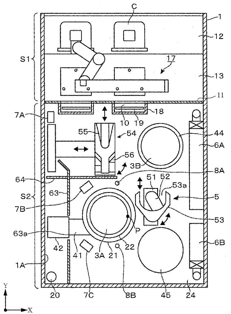
[0109] Such as Figure 14 As shown, the simulation of the gas flow velocity was performed using a model in which the wafer boat 3 , the first to third exhaust ducts 7A to 7C, and the gas supply nozzles 8A and 8B are provided in the loading area S2 . At this time, it is assumed that air flow is supplied as indicated by an arrow from the right side of the loading area S2. In addition, the length of the X direction of the loading area S2 was 1000 mm, the length of the Y direction of the loading area S2 was 1800 mm, and the height of the loading area S2 was 1800 mm. It is assumed that 100 wafers W having a diameter of 300 mm are placed on the wafer boat 3 . In addition, the distance d1 between the exhaust port 71 of the second exhaust air duct 7B and the outer edge of the cover body 21 is set to 15 mm, and the distance d1 between the exhaust port 71 of the third exhaust air duct 7C and the outer edge of the cover body 21 is set to 15 mm. The distance d2 between the edges was set...
Embodiment 2
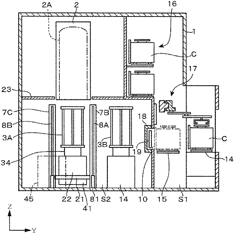
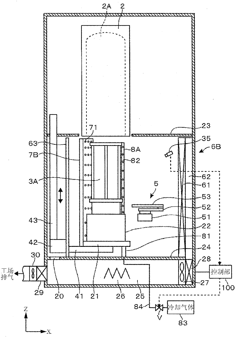
[0115] use Figure 1 ~ Figure 3 In the shown device, 100 wafers W with a size of 300 mm are placed in the wafer boat 3, and heat treatment is performed at 700° C. in the heat treatment furnace 2, for example, for 60 minutes, and then the wafer boat 3 is unloaded. The temperatures of the upper side, the central part, and the lower side of the atmosphere above the wafer transfer mechanism 54 were measured. The upper side of the upper atmosphere of the wafer transfer mechanism 54 is set to the upper side of 1500 mm from the bottom plate 24, the central part is set to the upper side of 1000 mm from the bottom plate 24, and the lower side is set to the upper side of 500 mm from the bottom plate 24. side. At this time, the distance between the exhaust hole 71 of the second exhaust air duct 7B and the outer edge of the cover body 21 is set to 15mm, and the distance between the third exhaust air duct 7C and the outer edge of the cover body 21 is set to The distance between each gas ...
Embodiment 3
[0120] As in Example 2, the temperature of the wafer W placed on the wafer boat 3A was measured. The temperature measurement is performed on a plurality of wafers W placed at several different positions in the height direction of the wafer boat 3A, Figure 28 The mean value of the measurement results is indicated by the solid line. In addition, as Comparative Example 3, the data of the case where the exhaust air ducts 7A to 7C, the cooling gas nozzles 8A and 8B, and the partition plate 64 are not provided are shown by dotted lines. exist Figure 28 In , the horizontal axis is time, the vertical axis is temperature, and the unloading start time is 0 minutes.
[0121] As a result, it was found that the time for the wafer to cool down to 80°C after unloading in Example 3 was about 3 minutes shorter than the time for the wafer to cool down to 80°C after unloading in Comparative Example 3, confirming that this embodiment can The cooling time of the unloaded wafer W is shortened....
PUM
 Abstract
Description
Claims
Application Information
 - R&D
- Intellectual Property
- Life Sciences
- Materials
- Tech Scout
- Unparalleled Data Quality
- Higher Quality Content
- 60% Fewer Hallucinations
Browse by: Latest US Patents, China's latest patents, Technical Efficacy Thesaurus, Application Domain, Technology Topic, Popular Technical Reports.
© 2025 PatSnap. All rights reserved.Legal|Privacy policy|Modern Slavery Act Transparency Statement|Sitemap|About US| Contact US: help@patsnap.com


